System for Vital Brake Interface with Real-Time Integrity Monitoring

a technology of integrity monitoring and vital brakes, applied in the field of railroads, can solve problems such as potential danger, brake activation, and added to the expense of operating the train

a technology of integrity monitoring and vital brakes, applied in the field of railroads, can solve problems such as potential danger, brake activation, and added to the expense of operating the train

US20100256843A1Inactive Publication Date: 2010-10-07LOCKHEED MARTIN CORP

Image

  • System for Vital Brake Interface with Real-Time Integrity Monitoring
  • System for Vital Brake Interface with Real-Time Integrity Monitoring
  • System for Vital Brake Interface with Real-Time Integrity Monitoring

Examples


Embodiment Construction

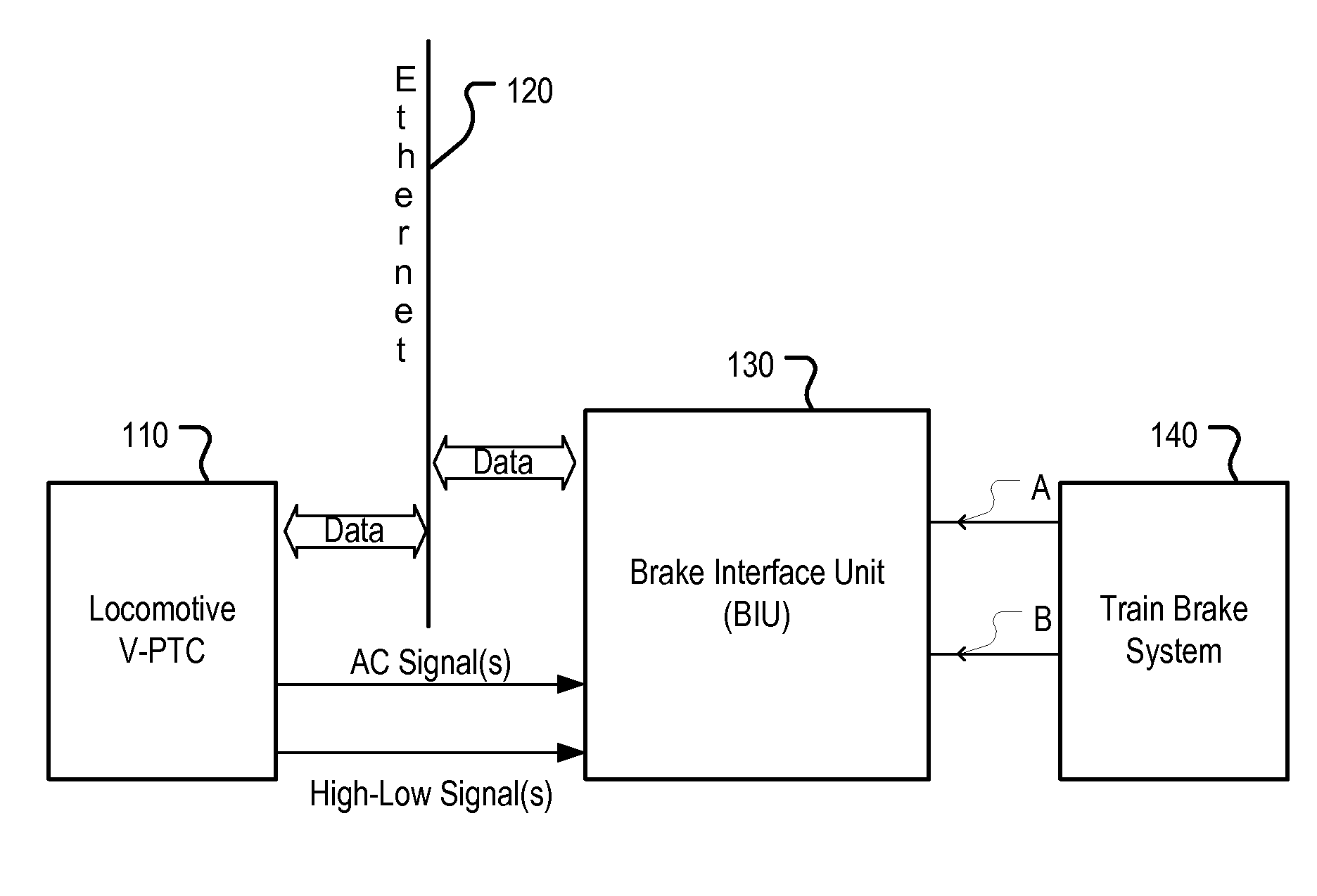
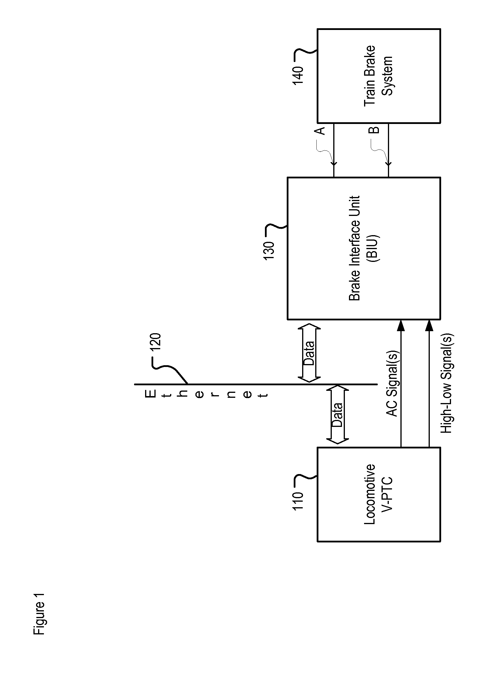
[0038]FIG. 1 depicts a train control system including a brake interface unit in accordance with the illustrative embodiment of the present invention. The train control system comprises, vital positive train control (V-PTC) 110, brake interface unit (BIU) 130, and train brake system 140.

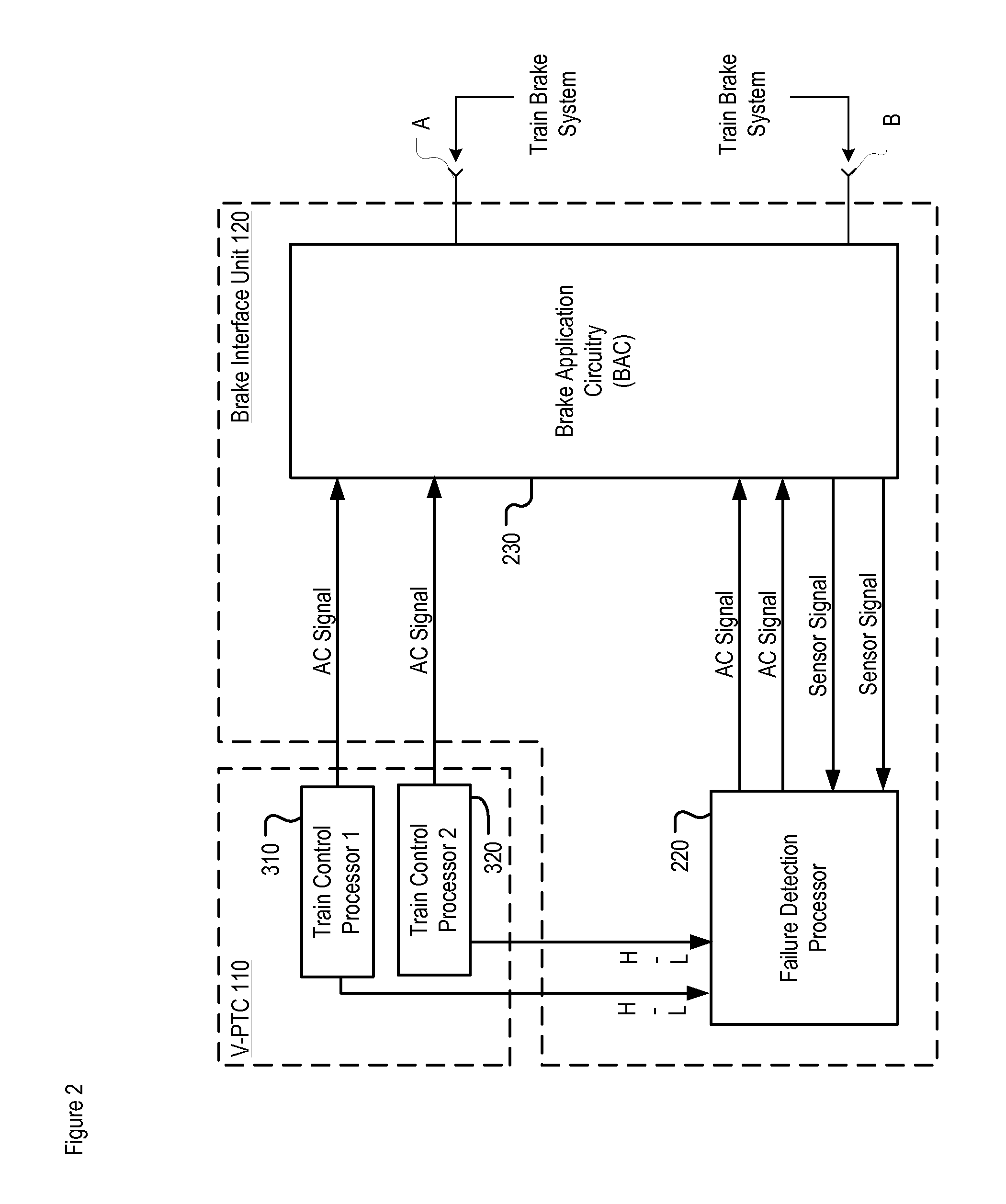
[0039]Brake interface unit (BIU) 130 is interface for engaging the brakes on a train. It is connected to at least one train control processor that is in control of a train's braking. In accordance with the illustrative embodiment of the present invention, brake interface unit (BIU) 130 performs one or more of the following six (6) functions:

[0040](1) carry instructions of a train control processor to apply the brakes on a train;

[0041](2) detect a failure in the train control processor;

[0042](3) detect a failure in its own circuitry;

[0043](4) apply the brakes when a failure is found;

[0044](5) perform self diagnostics; and

[0045](6) perform any other action that is specified in the remainder of this disc...


PUM


Abstract

A train control system comprising a vital brake interface unit that is disposed between the train control processors and the braking system. The brake interface unit ensures that any failure in the control processors or the interface itself is detectable and, when detected, causes the system to fail safely (i.e., the train's brakes are applied). By virtue of the use of redundant circuitry paths, the vital braking interface unit enables real-time verification of system circuitry without actually applying the train's brakes.

Description

CROSS-REFERENCE TO RELATED APPLICATIONS[0001]This application claims the benefit of U.S. provisional application Ser. No. 61 / 166,163, filed Apr. 2, 2009, entitled System for Vital Brake Interface with Real-Time Integrity Monitoring (Attorney Docket 711-264us), which is also incorporated by reference.FIELD OF THE INVENTION[0002]The present invention relates to railroads in general, and, more particularly, to railroad braking systems.BACKGROUND OF THE INVENTION[0003]In the early days of railroads, train brakes were operated by brakemen who would manually activate and deactivate the brakes on the train. This added to the expense of operating the train and ultimately led to the development of air brakes.[0004]In an air brake system, pressurized air is distributed via an air brake pipe system to each brake cylinder on a train. The brake calipers are designed so that the brake shoes engage the train wheel to stop the train if the pressurized air flow is disrupted. These systems typically ...

Claims


Application Information

Patent Timeline
07 Oct 2010
Publication
US20100256843A1
IPC
B61L99/00; G06F19/00; B60T17/18; B60T17/22
CPC
B60T17/228; B61L3/008; B61L27/0027; B61L15/0063; B61L27/0022; B61L15/0036; B61L27/14; B61L27/16
Inventors
BERGSTEIN, HARVEY; METZGER, THOMAS R.