Forefoot catapult for athletic shoes

a technology for athletic shoes and catapults, applied in the field of footwear, can solve the problems of improper positioning of devices, adverse physiological effects of devices on the foot, and the ineffectiveness of heel springs for energy storage and return, and achieve the effect of increasing the spring load

Active Publication Date: 2010-10-14
ATHLETIC PROPULSION LABS
View PDF74 Cites 20 Cited by
  • Summary
  • Abstract
  • Description
  • Claims
  • Application Information

AI Technical Summary

Benefits of technology

[0017]A method in accordance with an embodiment of the present invention allows for storing and returning energy during a propulsion phase of a gait cycle in a human step using a catapult device in a shoe including two plates and a spring that biases the two plates apart from each other. In various embodiments, the method comprises applying, with a foot, a force on at least one of the two plates that is positioned in the shoe beneath a forefoot portion of the foot, so as to move the two plates together and increase a loading of the spring, and launching the foot due to the two plates being moved apart by the spring as the foot is being lifted.

Problems solved by technology

Because energy stored in the contact phase via a heel spring is dissipated by the time the propulsion phase begins, heel springs have not proven effective for energy storage and return.
In addition to not being effective in the propulsion phase, such devices can have adverse physiological effects on the foot if not properly positioned.

Method used


Image

  • Forefoot catapult for athletic shoes
  • Forefoot catapult for athletic shoes
  • Forefoot catapult for athletic shoes

Examples


Embodiment Construction

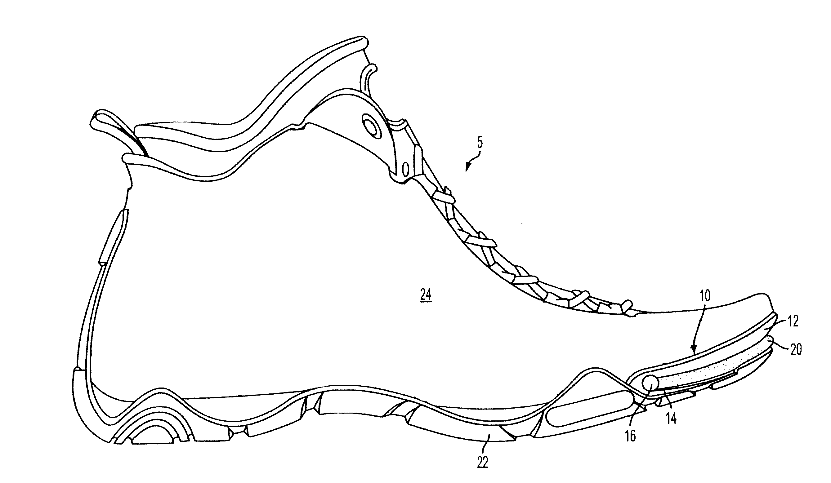
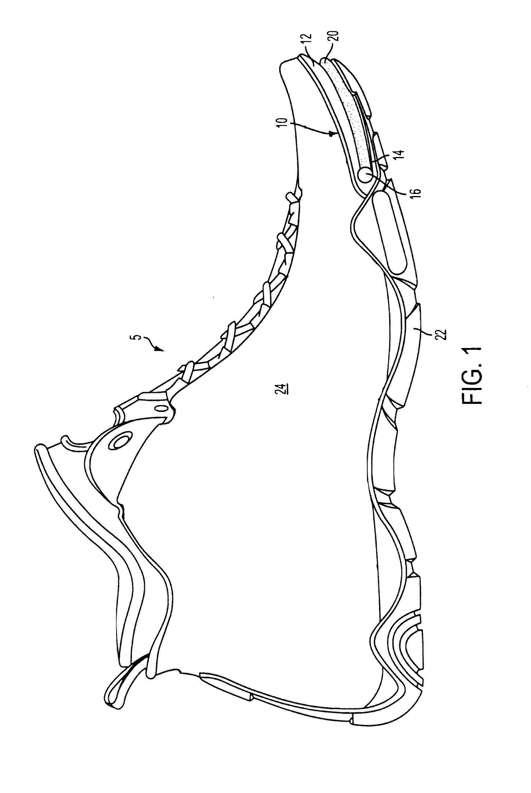
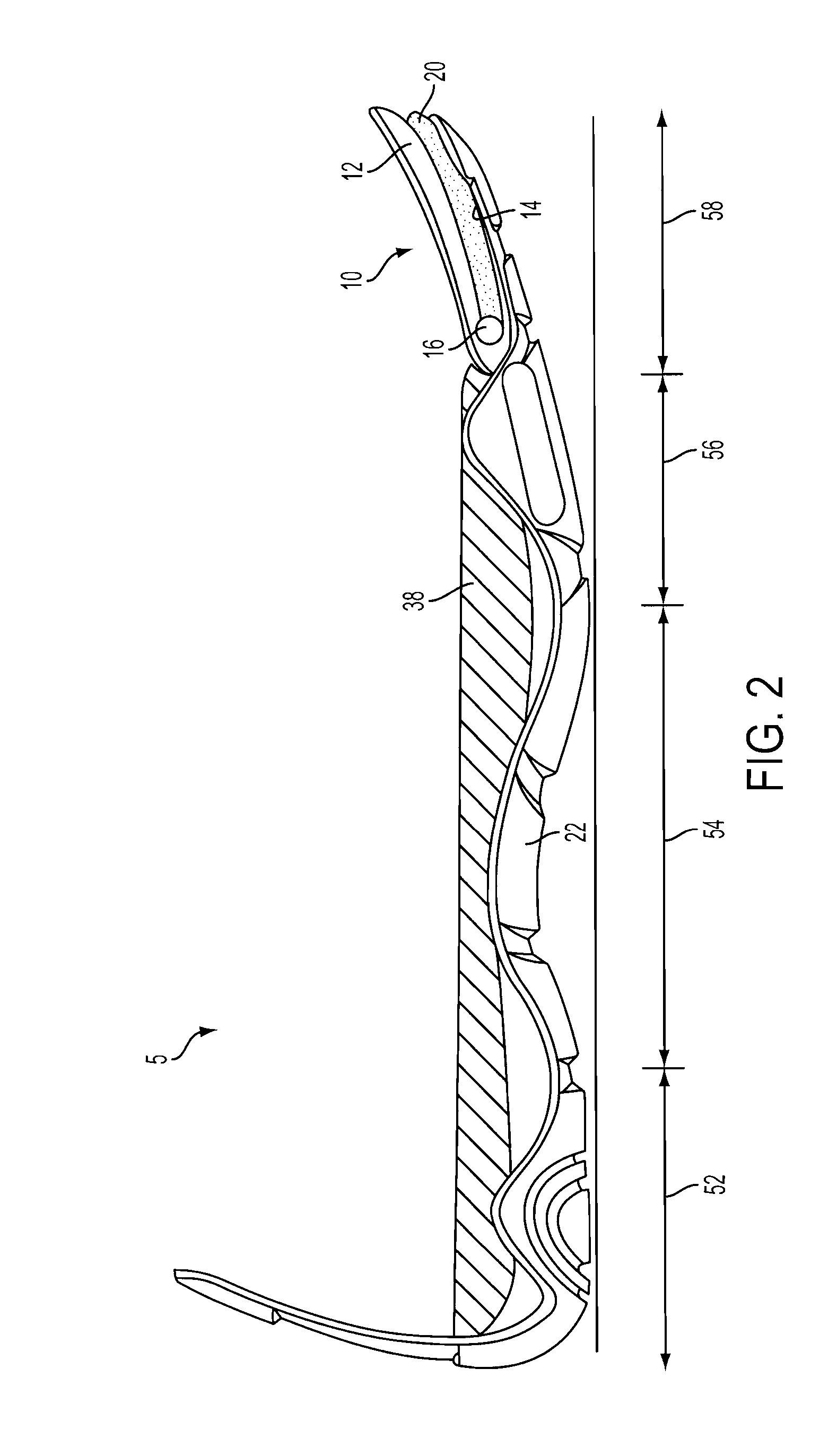
[0034]Referring to FIG. 1, an athletic shoe 5 is provided with a catapult device 10 according to an embodiment of the present invention. The catapult device 10 is mounted in an outsole 22 of the shoe 5, as shown in more detail in FIG. 2. The catapult device 10 includes a top plate 12 and a bottom plate 14 that are hinged together via a pin 18 (or similar means), as shown in FIG. 5. In various embodiments, the plates 12 and 14 are designed such that they have a very limited motion around a hinge axis. Also, in various embodiments, in a neutral position the plates 12 and 14 are parallel to each other, forming what might be explained as a duck-bill, as shown in FIGS. 3 and 4. In some embodiments, the plates 12 and 14 have a limited motion that allows movement toward one another but not opening beyond (any more than) the two plates being parallel to each other.

[0035]With reference to FIG. 1, various materials could be used for the plates 12 and 14, including polymer, block polymer, mono...


PUM


Abstract

An athletic shoe includes an upper, an outsole, a pair of hinged plates, and a spring. The pair of hinged plates are attached between the outsole and the upper in a forefoot portion of the shoe, and the spring biases the plates apart, so that energy is stored and returned during a propulsion phase of a gait cycle in a human step. Foam may be disposed between the plates. A shroud may enclose an outer periphery of the plates. An adjustable torsion spring may be disposed in a hinge portion of the plates, and one or more wave springs may be disposed between the plates.

Description

CROSS-REFERENCE TO RELATED PATENT APPLICATIONS[0001]This application claims the benefit of U.S. Provisional App. Ser. No. 61 / 168,533, entitled “Forefoot Catapult for Athletic Shoes”, filed Apr. 10, 2009, the entire contents of which are incorporated by reference herein.BACKGROUND OF THE INVENTION[0002]1. Field of the Invention[0003]Embodiments of the present invention relate in general to footwear, and particularly to energy absorption and return systems for use in athletic footwear.[0004]2. Related Art[0005]In prior U.S. Pat. Nos. 5,437,110 and 5,596,819, issued in the names of two of the inventors herein, a discussion was provided of the desirability of providing adjustable foot-strike energy shock absorption and return. Those patents disclosed the use of a device disposed in the midsole of a shoe under the heel. The device used an adjustable mechanism to store and return to the wearer's foot shock energy experienced during walking or running.[0006]Those prior patents discussed a ...

Claims


Application Information

Patent Timeline
Patent Type & Authority Applications(United States)
IPC IPC(8): A43B5/00A43B13/28A43B13/18
CPCA43B13/182A43B13/16Y02P30/40
Inventor BEMIS, JONGOLDSTON, MARKGOLDSTON, ADAMGOLDSTON, RYAN
Owner ATHLETIC PROPULSION LABS
Why Eureka
Try Eureka