Vibration wave motor and driving apparatus using vibration wave motor

a technology of vibration wave motor and driving apparatus, which is applied in the direction of piezoelectric/electrostrictive/magnetostrictive devices, instruments, mountings, etc., can solve the problems of increasing the number of parts, reducing the ease of assembly, and reducing the average driving speed, so as to reduce the average driving speed and increase the number of parts.

Active Publication Date: 2019-06-13
CANON KK
View PDF0 Cites 3 Cited by
  • Summary
  • Abstract
  • Description
  • Claims
  • Application Information

AI Technical Summary

Benefits of technology

[0003]When the mass of a member to be driven is large, it is required to increase the spring load of the plate spring in the ultrasonic motor in Japanese Patent Application Laid-Open No. 2015-126692. In this case, the increase in spring load degrades ease of assembly, and hence it is required to limit the spring load to a certain spring load. However, there is a problem in that it is required to suppress an acceleration degree at a time of acceleration and deceleration in order to limit the spring load, resulting in a decrease in average driving speed. Further, in the ultrasonic motor in Japanese Patent Application Laid-Open No. 2016-101022, when a plurality of vibrators are used, each vibrator needs to have a pressurizing unit, resulting in increase in number of parts.

Problems solved by technology

In this case, the increase in spring load degrades ease of assembly, and hence it is required to limit the spring load to a certain spring load.
However, there is a problem in that it is required to suppress an acceleration degree at a time of acceleration and deceleration in order to limit the spring load, resulting in a decrease in average driving speed.
Further, in the ultrasonic motor in Japanese Patent Application Laid-Open No. 2016-101022, when a plurality of vibrators are used, each vibrator needs to have a pressurizing unit, resulting in increase in number of parts.

Method used


Image

  • Vibration wave motor and driving apparatus using vibration wave motor
  • Vibration wave motor and driving apparatus using vibration wave motor
  • Vibration wave motor and driving apparatus using vibration wave motor

Examples


application example 1

[0029]Next, the configuration and operation of a lens driving apparatus 210 according to Application Example 1 employing the vibration wave motor 100 according to the embodiment of the present invention are described with reference to FIG. 5. FIG. 5 is a view of the lens driving apparatus 210, in which the vibration wave motor 100 is incorporated, when viewed in the optical axis direction (X-direction).

[0030]The moving-side frame member 23 of the vibration wave motor 100 is connected to a lens holder 211 through a connecting portion 211c formed in the lens holder 211. The lens holder 211 is configured to hold an optical lens 212, and is fitted with a first guide bar 213 in a guide portion 211a formed in the lens holder 211 to be guided in a straight line in the X-direction. The first guide bar 213 is fixed to a fixed portion (not shown) as indicated by “FIX” in FIG. 5. Further, the lens holder 211 has an elongated hole 211b at a position that is substantially opposed to the guide po...

application example 2

[0033]Next, the configuration of an image pickup apparatus according to Application Example 2 employing the lens driving apparatus 210 including the vibration wave motor 100 according to the embodiment of the present invention is described with reference to FIG. 6. In FIG. 6, an image pickup apparatus main body includes an image pickup lens unit 200 and a camera body 300. The camera body 300 includes an image pickup element 310, and the lens driving apparatus 210 is built in the image pickup lens unit 200. The vibration wave motor 100 provided in the lens driving apparatus 210 can drive the optical lens 212 being a focusing lens substantially in parallel to the X-direction that is an optical axis direction. The optical lens 212 being a focusing lens is moved in a direction that is substantially parallel to an optical axis at a time of image pickup, and a subject image is formed at a position of the image pickup element 310, thereby being capable of generating a focused image.

[0034]T...


PUM


Abstract

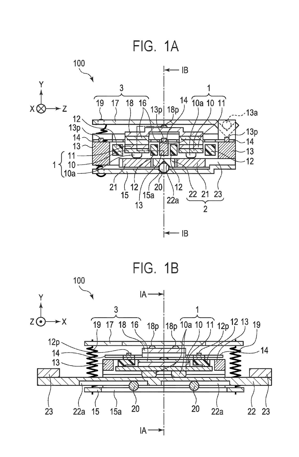
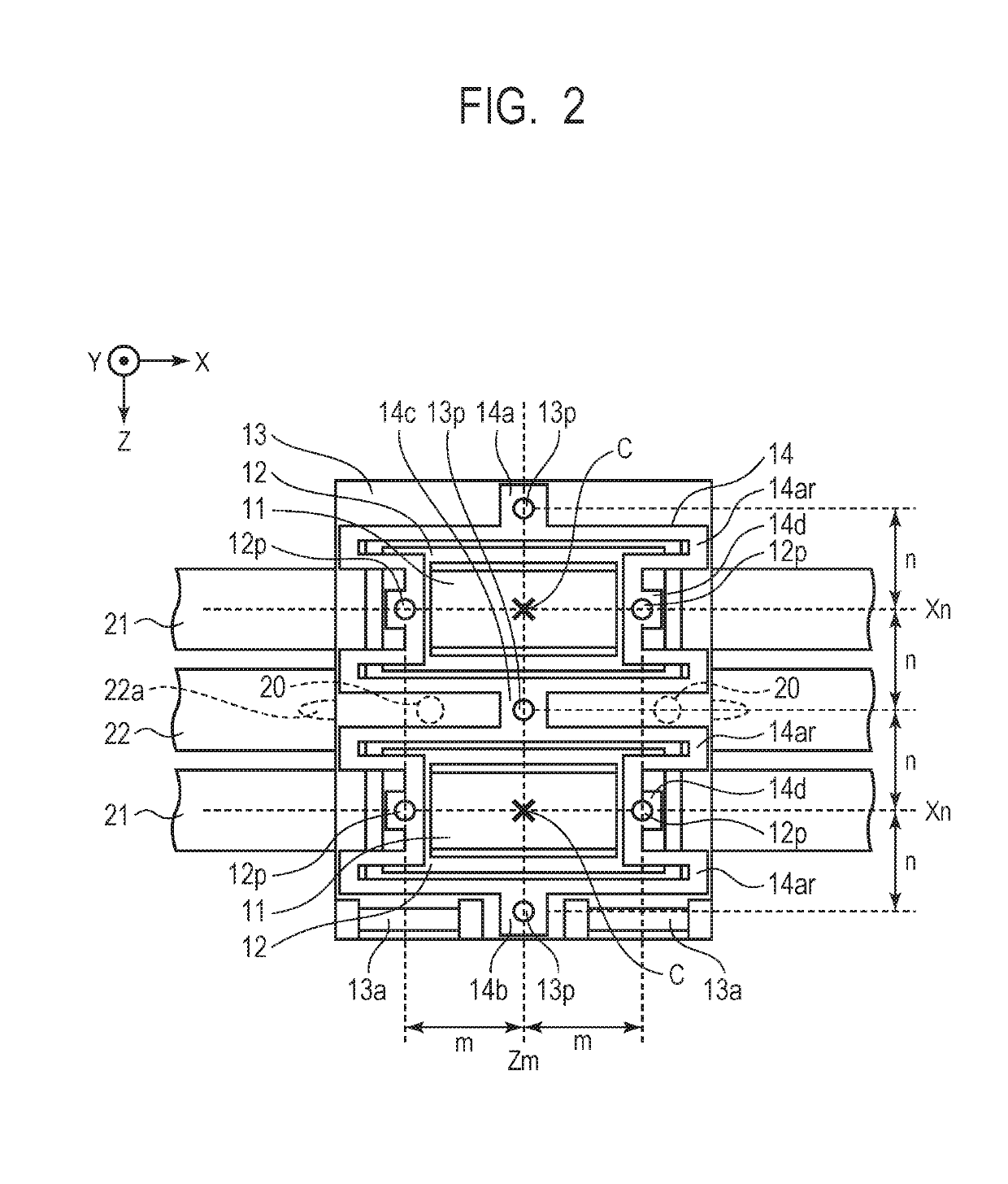
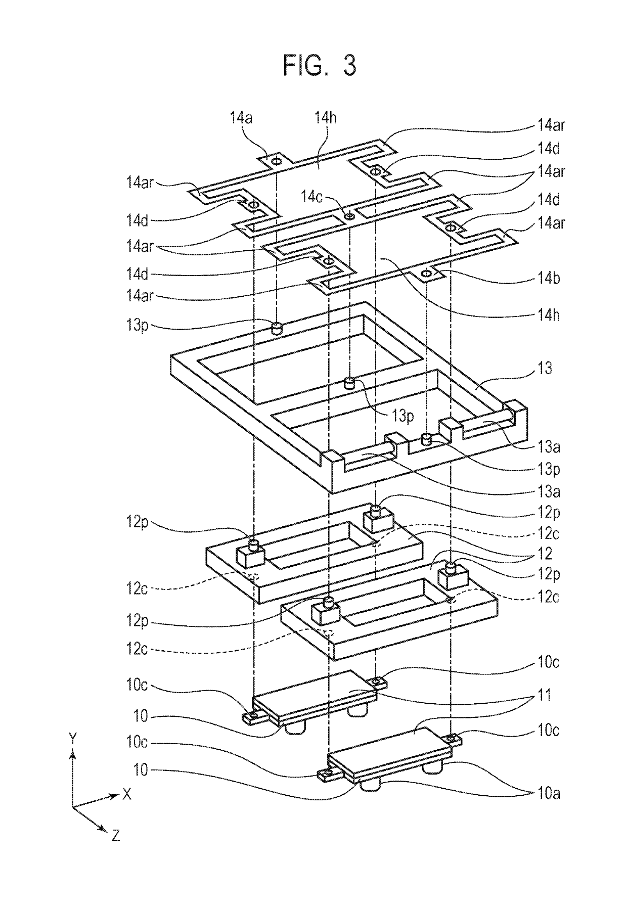
A vibration wave motor including: a vibrator; a first holding member configured to hold the vibrator; a second holding member; an elastic coupling member configured to couple the first holding member and the second holding member to each other; a friction member; and a pressurizing unit, wherein the vibrator and the friction member relatively move due to vibration of the vibrator, wherein the elastic coupling member includes a first coupling portion and a second coupling portion, and wherein one of the first coupling portion and the second coupling portion is arranged on a straight line that is parallel to a direction of the relative movement and passes through a pressurizing gravity center and another of the first coupling portion and the second coupling portion is arranged on a straight line that is orthogonal to the direction of the relative movement and passes through the pressurizing gravity center.

Description

BACKGROUND OF THE INVENTIONField of the Invention[0001]The present invention relates to a vibration wave motor and a driving apparatus using the vibration wave motor.Description of the Related Art[0002]An ultrasonic motor having features of a small size and light weight, high driving force, a wide speed range, and quiet drive has been adopted in a lens barrel of an optical apparatus and the like. In an ultrasonic motor disclosed in Japanese Patent Application Laid-Open No. 2015-126692, a base having a vibrator fixed thereto and a vibrator holding member are coupled to each other through use of a plate spring provided therebetween without backlash by being urged in a relative movement direction. Further, according to description in Japanese Patent Application Laid-Open No. 2016-101022, an ultrasonic motor disclosed therein is configured to drive a drive part by generating larger driving force through use of a plurality of vibrators, for example, when the weight of the drive part is l...

Claims


Application Information

Patent Timeline
Patent Type & Authority Applications(United States)
IPC IPC(8): H02N2/02H02N2/04G02B7/04
CPCH02N2/026H02N2/028H02N2/04G02B7/04H01L41/1876H02N2/0055G02B7/08H02N2/006G03B2205/0061H10N30/8554
Inventor NAKABAYASHI, MAIYAMASAKI, RYOYAMAMOTO, YASUFUMININOMIYA, SHUNSUKE
Owner CANON KK
Why Eureka
Try Eureka