Thin film thermoelectric devices for power conversion and cooling

a thermoelectric device and thin film technology, applied in the direction of thermoelectric device manufacture/treatment, thermoelectric device details, lighting and heating apparatus, etc., can solve the problems of low efficiency, limited application of thermoelectric devices in cooling and refrigeration, and low efficiency of thermoelectric conversion thermoelectric devices, etc., to achieve low external heat-flux and high internal heat-flux

Inactive Publication Date: 2010-10-14
NEXTREME THERMAL SOLUTIONS
View PDF70 Cites 84 Cited by
  • Summary
  • Abstract
  • Description
  • Claims
  • Application Information

AI Technical Summary

Benefits of technology

[0019]Accordingly, one object of some embodiments of the present invention is to provide a thermoelectric device in which there is a hi...

Problems solved by technology

Accordingly, there is a drawback that thermoelectric conversion efficiency is low as compared with the other direct energy conversion systems such as for example a fuel cell device.
Low efficiencies have also limited the application of thermoelectric devices in cooling and refrigeration applications.
While Chen et al. describe that thermoelectric coolers may be any suitable thermoelectric coolers such as those supplied by Melcor under catalog number CP 2-127-06L, the efficiency of these coolers, like those of...

Method used


Image

  • Thin film thermoelectric devices for power conversion and cooling
  • Thin film thermoelectric devices for power conversion and cooling
  • Thin film thermoelectric devices for power conversion and cooling

Examples


Embodiment Construction

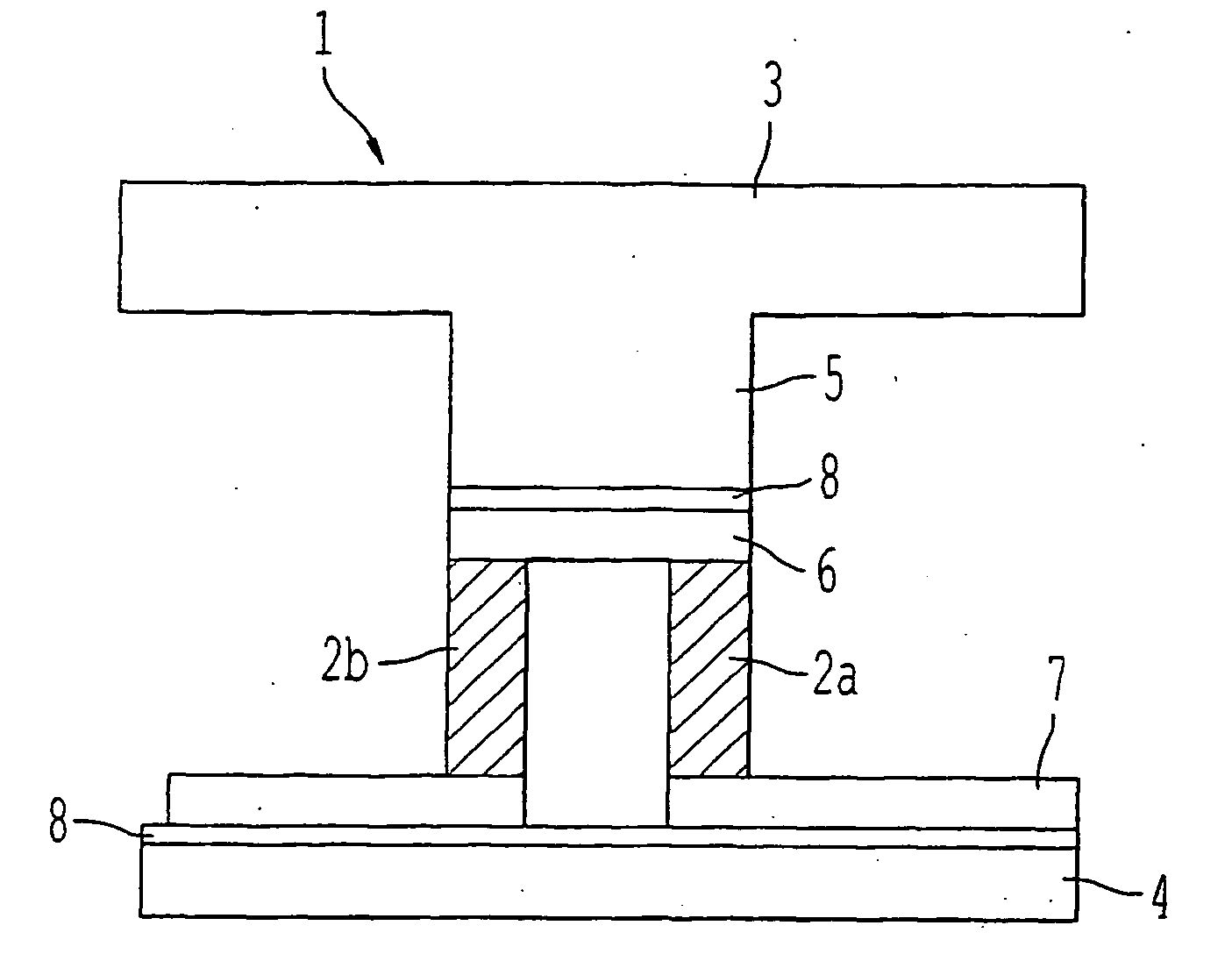
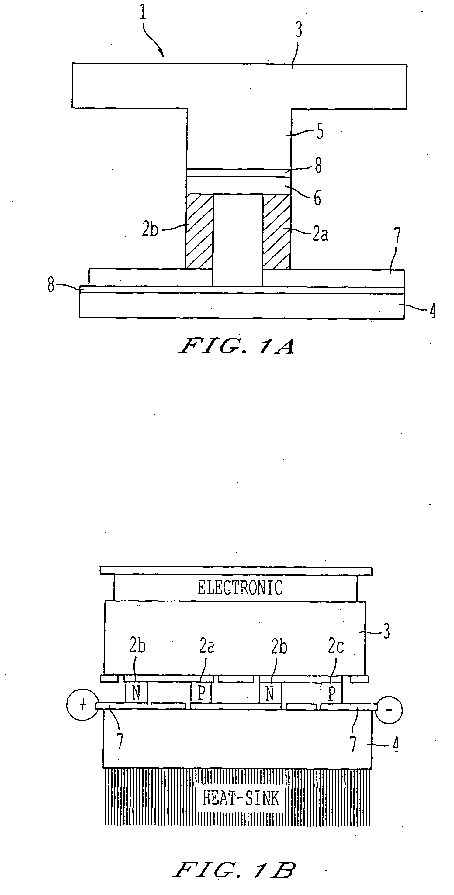
[0044]Referring now to the drawings, wherein like reference numerals designate identical, or corresponding parts throughout the several views, and more particularly to FIG. 1A thereof, FIG. 1A depicts a schematic of one embodiment of a thermoelectric device according to some embodiments of the present invention. As shown in FIG. 1A, a thermoelectric device 1 of some embodiments of the present invention includes a thermoelectric pair of n and p-type thermoelements 2a and 2b, respectively. The thermoelectric pair is connected thermally in parallel for heat conduction and electrically in series for electrical conduction. The thermoelectric pair of n and p-type thermoelements 2a and 2b are electrically adjoined together on the side coupled to an upper side header 3 by electrical connection 6, and are electrically connected separately on the side coupled to a lower side header 4 by electrical connection 7. As shown illustratively in FIG. 1A, the thermoelectric pair of n and p-type thermo...


PUM


Abstract

A thermoelectric device having at least one thermoelectric unit including at least one thermoelectric pair of n-type and p-type thermoelements, a first header coupled to one side of the thermoelectric pair, and a second header coupled to a second side of the thermoelectric pair. The thermoelectric pair has a thermal conduction channel area smaller than an area of the first header or the second header such that the thermal conduction area is a fraction of the area of the first header or the second header.

Description

RELATED APPLICATIONS[0001]The present application claims the benefit of priority as a continuation-in-part of U.S. application Ser. No. 11 / 406,100 filed on Apr. 18, 2006 which claims priority as a continuation-in-part of International Application No. PCT / US2004 / 041431 (designating the United States) filed on Dec. 13, 2004, which claims the benefit of priority from U.S. Provisional Application No. 60 / 528,479 filed Dec. 11, 2003. U.S. application Ser. No. 11 / 406,100 also claims the benefit of priority from U.S. Provisional Application No. 60 / 672,330 filed Apr. 18, 2005. The present application thus claims the benefit of priority from U.S. application Ser. No. 11 / 406,100; International Application No. PCT / US2004 / 041431; U.S. Provisional Application No. 60 / 528,479; and U.S. Provisional Application No. 60 / 672,330. The disclosures of each of the above referenced U.S. Utility, U.S. Provisional, and International PCT Applications are hereby incorporated herein in their entirety by reference...

Claims


Application Information

Patent Timeline
IPC IPC(8): F25B21/02
CPCH01L23/38H01L35/00H01L35/04H01L35/30H01L35/32H01L35/325H01L2924/0002H01L35/34H01L2924/3011H01L2924/00H10N10/81H10N19/101H10N10/00H10N10/13H10N10/01H10N10/17
Inventor VENKATASUBRAMANIAN, RAMAO'QUINN, BROOKS C.SIIVOLA, EDWARD P.COONLEY, KIP D.ADDEPALLI, PRATIMAALLEY, RANDALL G.POSTHILL, JOHNCOLPITTS, THOMASREDDY, ANIL J.CAYLOR, JAMES CHRISTOPHERTHOMAS, PETER
Owner NEXTREME THERMAL SOLUTIONS
Why Eureka
Try Eureka