Motor

Inactive Publication Date: 2010-10-14
SUNONWEALTH ELECTRIC MACHINE IND
View PDF8 Cites 5 Cited by
  • Summary
  • Abstract
  • Description
  • Claims
  • Application Information

AI Technical Summary

Benefits of technology

[0007]The primary objective of the present invention is to provide a motor including a balancing member that has an optimal magnetically attracting spacing to the permanent magnet to assure stable rotation of a rotor of the motor.

Problems solved by technology

Specifically, if the magnetically attracting spacing D is too large, the magnetically attracting effect between the balancing plate 94 and the permanent magnet 932 could be too small, such that the rotor 93 could not rotate stably, leading to wobbling of the rotor 93 and noise and shortening the service life of the motor 9.
On the other hand, if the magnetically attracting spacing D is too small, the magnetically attracting effect between the balancing plate 94 and the permanent magnet 932 could be too large, such that rotation of the rotor 93 could be adversely affected.
Furthermore, operations of the permanent magnet 932 and the balancing plate 94 could interfere with each other, adversely affecting operational performance of the motor 9.

Method used


Image

  • Motor
  • Motor
  • Motor

Examples


first embodiment

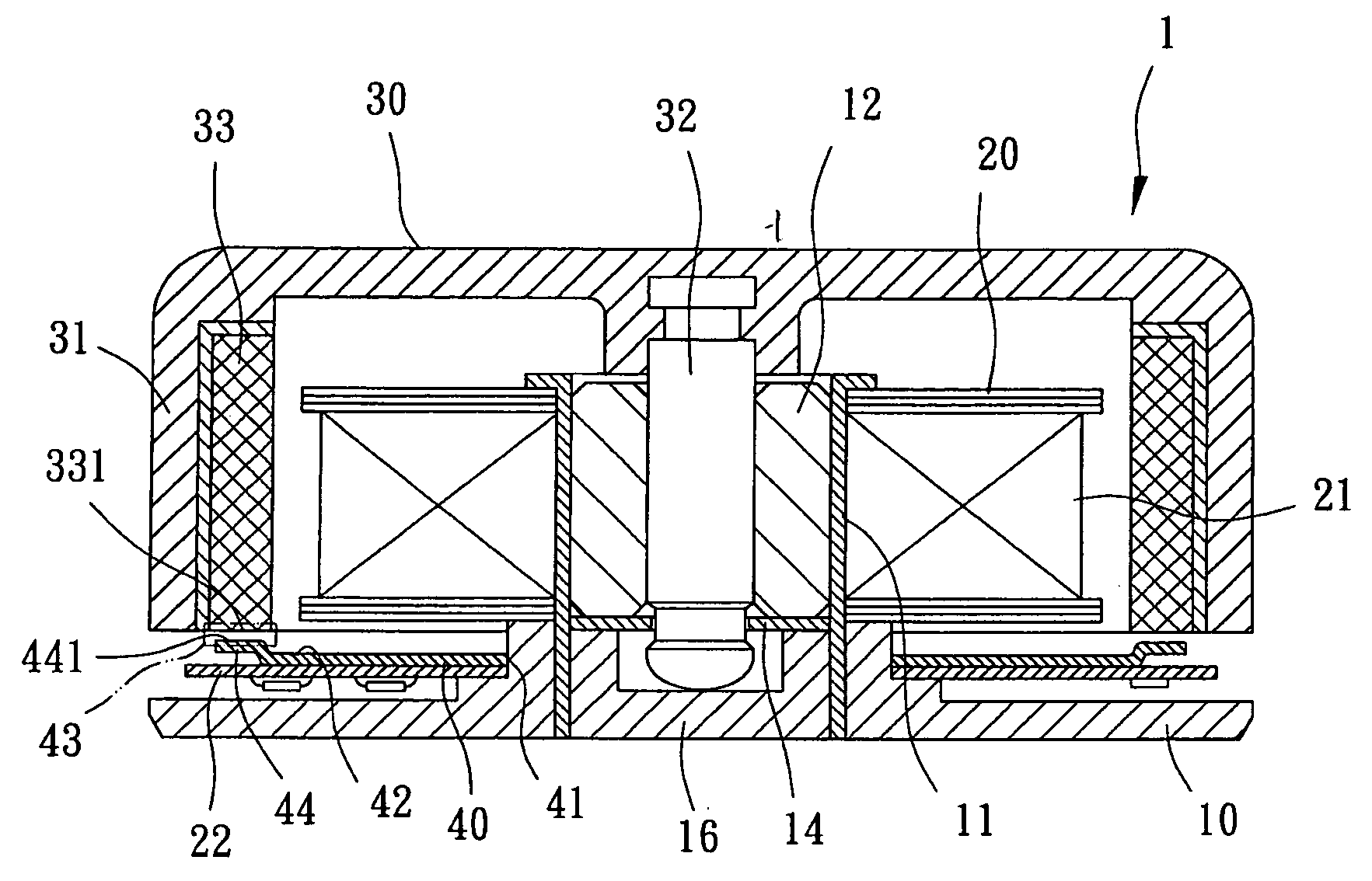
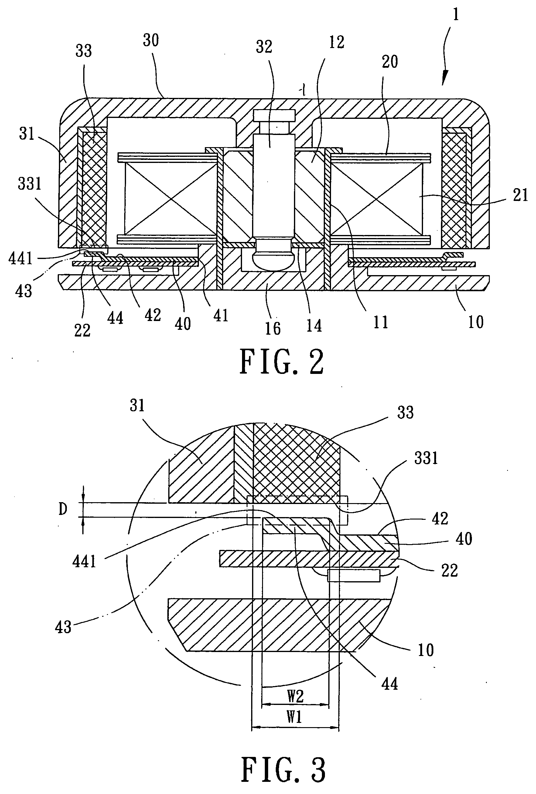
[0030]A motor 1 of a first embodiment according to the preferred teachings of the present invention is shown in FIGS. 2-4 of the drawings. According to the preferred form shown, the motor 1 includes a base 10, a stator 20, a rotor 30, and a balancing member 40.

[0031]According to the preferred form shown, the base 10 includes an axle tube 11 extending along an axis and receiving a bearing 12, a retainer ring 14, and an end cap 16. The base 10 can be in the form of a housing for a fan.

[0032]The stator 20 is mounted around an outer periphery of the axle tube 11 and includes a winding 21 and a circuit board 22 electrically connected to the winding 21. The winding 21 can be a radial winding or an axial winding.

[0033]The rotor 30 includes a hub 31, a shaft 32, and a permanent magnet 33. The hub 31 can include a plurality of blades on an outer periphery thereof, so that the rotor 30 can be utilized as an impeller of a fan. The shaft 32 is rotatably extended through the axle tube 11 of the ...

third embodiment

[0043]In the third embodiment, the balancing member 60 is mounted between the rotor 30 and the base 10. The balancing member 60 includes a plurality of arcuate sections 61 those are identical in structure and can be assembled together around the axle tube 11. Thus, the arcuate sections 61 can be mounted around the axle tube 11 and form a ring. Each arcuate section 61 includes an upper surface 62 facing the permanent magnet 33, with a magnetically conductive section 63 formed between the first magnetically conductive face 331 of the permanent magnet 33 and the upper face 62. Each arcuate section 61 further includes a magnetically attracting portion 64 formed in the magnetically conductive section 63 and having a second magnetically conductive face 641 between the upper surface 62 of the balancing member 60 other than the magnetically attracting portion 64 and the first magnetically conductive face 331 along the axis. The second magnetically conductive face 641 has a second width W2 i...


PUM


Abstract

A motor includes a base, a stator mounted to the base, a rotor rotatably coupled to the base, and a balancing member. The rotor includes a permanent magnet having a first magnetically conductive face with a first width in a radial direction. The balancing member includes an upper surface facing the permanent magnet. A magnetically conductive section is formed between the upper surface and the first magnetically conductive face. The balancing member further includes a magnetically attracting portion in the magnetically conductive section. The magnetically attracting portion includes a second magnetically conductive face having a second width in the radial direction. The second width is not greater than the first width. A magnetically attracting spacing is formed between the first and second magnetically conductive faces and in a range of 0.2-1.5 mm.

Description

BACKGROUND OF THE INVENTION[0001]1. Field of the Invention[0002]The present invention relates to a motor and, more particularly, to a motor including a balancing member for stabilizing rotation of a rotor of the motor.[0003]2. Description of the Related Art[0004]Motors with a balancing member have been proposed, and an example is disclosed in Taiwan Patent Publication No. 423760 entitled “Brushless D.C. Motor”. As shown in FIG. 1, such a motor 9 includes a base 91, a stator 92, a rotor 93, and a balancing plate 94. The base 91 includes an axle tube 911 around which the stator 92 is fixed. The rotor 93 includes a shaft 931 rotatably extending through the axle tube 911 and a permanent magnet 932. The balancing plate 94 is mounted to the base 91, with a magnetically attracting spacing D formed between the balancing plate 94 and the permanent magnet 932 to provide a magnetically attracting effect therebetween, so that the rotor 93 can rotate stably.[0005]The magnetically attracting spac...

Claims


Application Information

Patent Timeline
IPC IPC(8): H02K5/24
CPCH02K5/163H02K11/0073H02K7/09H02K5/24H02K11/33
Inventor HORNG, ALEX
Owner SUNONWEALTH ELECTRIC MACHINE IND
Why Eureka
Try Eureka