[0015]The method (1) is a method in which refractive power or an optical distance by the
cylindrical lens array 302 is changed to cause defocusing, thereby colors from the sub-pixels of the colors are mixed to prevent color unevenness and luminance unevenness. The method (2) is a method in which a diffuser plate is arranged between the display panel 301 and the cylindrical
lens array 302 to reduce color unevenness and luminance unevenness. However, in the methods (1) and (2), the sharpness of a displayed image is impaired by defocusing or diffusing light, and such impairment in sharpness of the displayed image may cause a reduction in a stereoscopic effect.
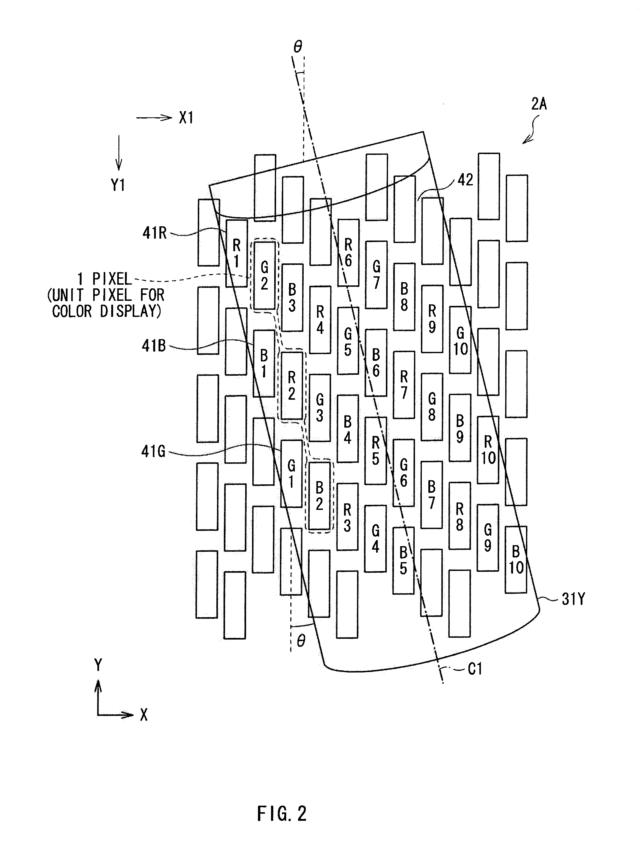
[0016]In the method (3), as illustrated in FIG. 18, a plurality of the sub-pixels 41R, 41G and 41B configuring unit pixels for color display are two-dimensionally used, and each unit pixel is configured of a combination of the sub-pixels 41R, 41G and 41B in a
diagonal direction. Moreover, the cylindrical lenses 303 are diagonally arranged along an angle of the combination of the sub-pixels. In FIG. 18, in a
plane parallel to a display surface of the display panel 301, the cylindrical axes (central axes) C1 of the cylindrical lenses 303 are inclined at an angle θ from a Y-axis direction in
configuration space (which coincides with the Y1-axis direction on the display panel 301 in an arrangement in FIG. 18). In addition, in FIG. 18, a combination of adjacent sub-pixels 41R, 41G and 41B to which the same number is assigned (Ri, Gi and Bi, i=1, 2, 3, . . . ) forms a unit pixel for color display. For example, a combination of sub-pixels (R2, G2 and B2) adjacent to one another in a
diagonal direction forms a unit pixel. In this method, the sub-pixels 41R, 41G and 41B configuring 1 pixel are arranged in a direction along the cylindrical axis C1 where the cylindrical lenses 303 do not have refractive power, so color unevenness does not occur. Moreover, the colors are mixed in a direction where the cylindrical lenses 303 do not have refractive power, so a change in luminance in a light-shielding section 42 is too small to be perceived, thereby luminance unevenness is substantially eliminated.
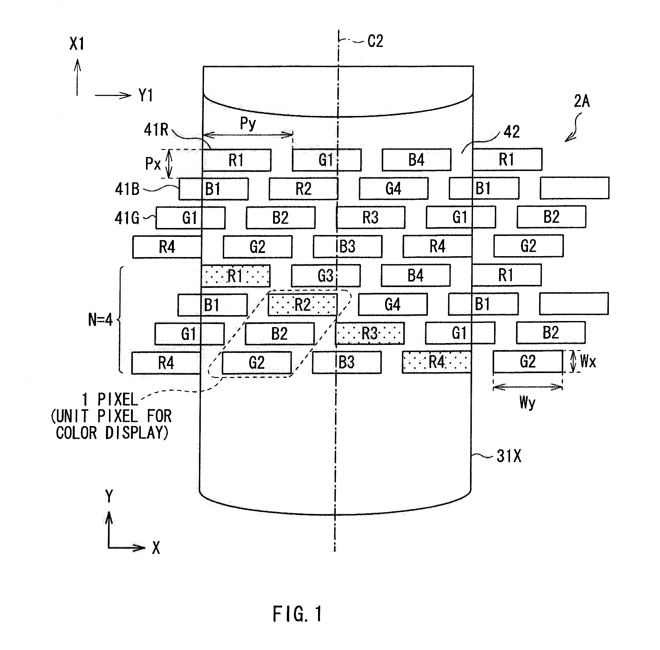
[0020]In the horizontal-striped arrangement, as illustrated in FIG. 19, a slanted lenticular system is used in order to eliminate luminance unevenness. In FIG. 19, the cylindrical axis (a central axis) C2 of the cylindrical lens 303X is inclined at an angle θ from the Y-axis direction in
configuration space (which coincides with the X1-axis direction on the display panel 301 in an arrangement in FIG. 19) in a
plane parallel to the display surface of the display panel 301. When the slanted lenticular system is used in order to eliminate luminance unevenness, in the case of the horizontal-striped arrangement, a sub-pixel
pitch in the horizontal direction is larger than that in the case of a vertical-striped arrangement. In other words, when a pixel
pitch in a shorter direction is Px, and a pixel
pitch in a longitudinal direction is Py (Py>Px), in the case of the vertical-striped arrangement, the sub-pixel pitch in the horizontal direction is Px, but in the case of the horizontal-striped arrangement, the sub-pixel pitch in the horizontal direction is Py. Therefore, the inclination angle θ of the cylindrical lens 303X increases, thereby it is difficult to separate
parallax images in the horizontal direction. In addition, in FIG. 19, a combination of adjacent sub-pixels 41R, 41G and 41B to which the same number is assigned (Ri, Gi and Bi, i=1, 2, 3, . . . ) form a unit pixel for color display. For example, a combination of sub-pixels (R2, G2 and B2) adjacent to one another in a
diagonal direction forms a unit pixel.
[0026]When the display panel with the pixel configuration illustrated in FIG. 21 is used, the same effects as those in the slanted lenticular system illustrated in FIG. 18 are obtained without diagonally arranging the cylindrical lens array 302 in order to eliminate color unevenness and luminance unevenness. However, even if such a display panel is used, in the case where the display is rotated by 90°, the light-shielding section 42 is continuously present in the vertical direction, thereby to cause luminance unevenness. As long as the light-shielding section 42 is present in the display panel, it is difficult to achieve a pixel configuration in which sub-pixels of each of the colors are successively arranged in both cases where the display is portrait-oriented and landscape-oriented. Moreover, in the case where the display is rotated by 90° from an arrangement state illustrated in FIG. 21, the pixel pitch in the horizontal direction is increased, so it is difficult to closely arrange pixels in the horizontal direction. Therefore, the slanted lenticular system is not suitable for the arrangement state, and it is difficult to eliminate luminance unevenness.
[0027]It is desirable to provide a stereoscopic display which is allowed to achieve favorable stereoscopic vision with less color unevenness and less luminance unevenness in both of a first arrangement state and a second arrangement state where the arrangement directions are different by 90° from each other.
[0031]In the stereoscopic display according to the embodiment of the invention, the arrangement direction of the cylindrical lenses and the combination of sub-pixels used as a unit pixel for color display are optimized depending on the arrangement state of the display panel, so favorable stereoscopic vision is achievable. In other words, in both of the first arrangement state and the second arrangement state where the arrangement directions of the display panel are by 90° from each other, favorable stereoscopic vision with less color unevenness and less luminance unevenness is achievable.

