Detachable framework used for winding optical fiber coil and a method of producing optical fiber coil

a technology of optical fiber coil and clamping frame, which is applied in the direction of cladded optical fiber, instruments, transportation and packaging, etc., can solve the problems of large gap between domestic and foreign level, inability to solve complete technical problems of optical fiber coil, and inability to use clamping in that application, so as to improve the temperature characteristics and vibration characteristics of optical fiber coil.

Active Publication Date: 2010-10-14
BEIJING AEROSPACE TIMES OPTICAL ELECTRONICS TECH
View PDF4 Cites 17 Cited by
  • Summary
  • Abstract
  • Description
  • Claims
  • Application Information

AI Technical Summary

Benefits of technology

[0011]The purpose in this invention is to overcome the disadvantage of the prior art to provide a detachable framework used for winding optical fiber coil and a method of producing optical fiber coil with this framework to improve the temperature characteristics and the vibration characteristics of optical fiber coil.

Problems solved by technology

But generally speaking, there is a great gap between the domestic and foreign level.
While, nonreciprocal phase difference between the two beams of light that propagates in opposite directions in the optical fiber coil not caused by rotation is one of the main error sources of the optical fiber gyro.
One of the main reasons why the high-precision optical fiber gyro in our country has not achieved breakthrough progress is that the technical problems in optical fiber coil have not been solved completely.
The main problem using the above solution is: in the practical situation, because of non-ideal winding (e.g., not complete symmetry of winding, optical fiber cross phenomenon of each layer in the optical fiber coil) and faultiness of curing technique (uneven thickness of the adhesive, long heat balance time of the optical fiber, non-linearity of the temperature grads and so on), the two pieces of optical fibers that are symmetrical relative to the middle point of the coil cannot undergo the complete same temperature field; because the impregnation of adhesive in curing technique makes the optical fiber in the optical fiber coil receive force unevenly and the thermal expansion and cold contraction of the framework apply stress on the optical fiber, and etc., the optical fiber coil also cannot undergo the complete same stress field; in the temperature and mechanics vibration environment, the optical fiber coil cannot satisfy the precision requirement of the high-precision optical fiber gyro yet, so the design and technique must be further improved based on the existing base to advance the performance of optical fiber coil, so as to improve the precision of optical fiber gyro.
But the implementation way by using clamp in that application is more complex, and the wheel hub and coil in framework are not separated, so the radial stress to the optical fiber coil produced by wheel hub can not be eliminated.

Method used


Image

  • Detachable framework used for winding optical fiber coil and a method of producing optical fiber coil
  • Detachable framework used for winding optical fiber coil and a method of producing optical fiber coil
  • Detachable framework used for winding optical fiber coil and a method of producing optical fiber coil

Examples


embodiment 3

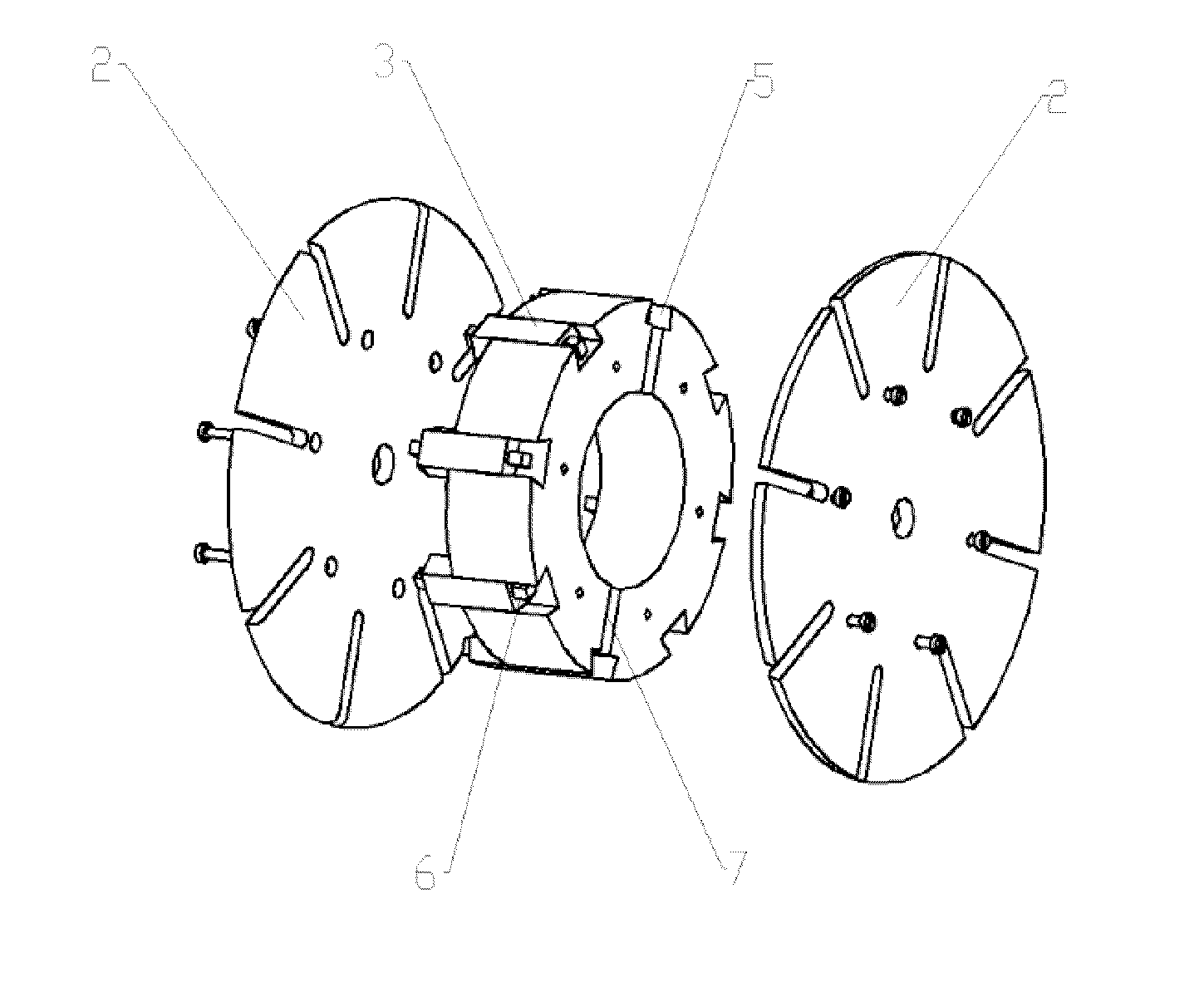
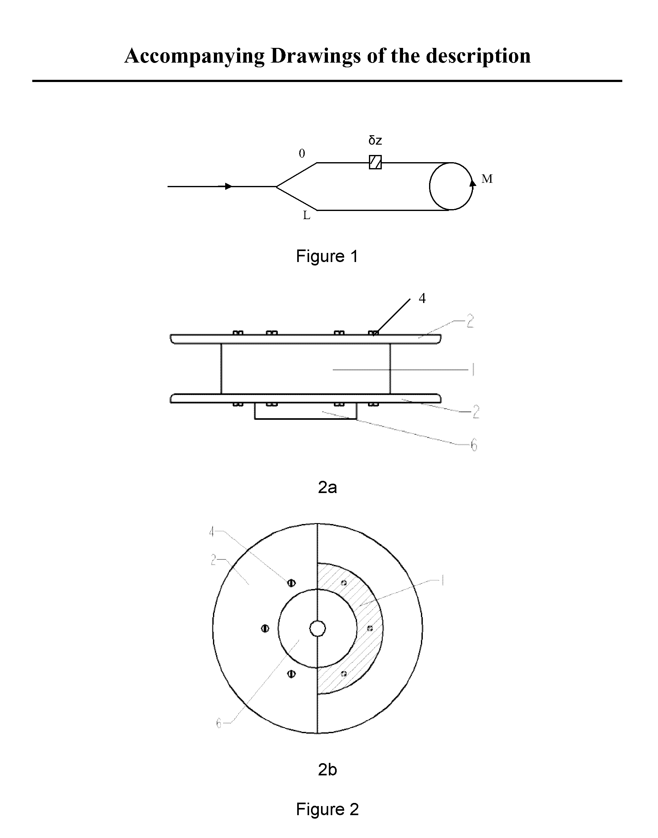
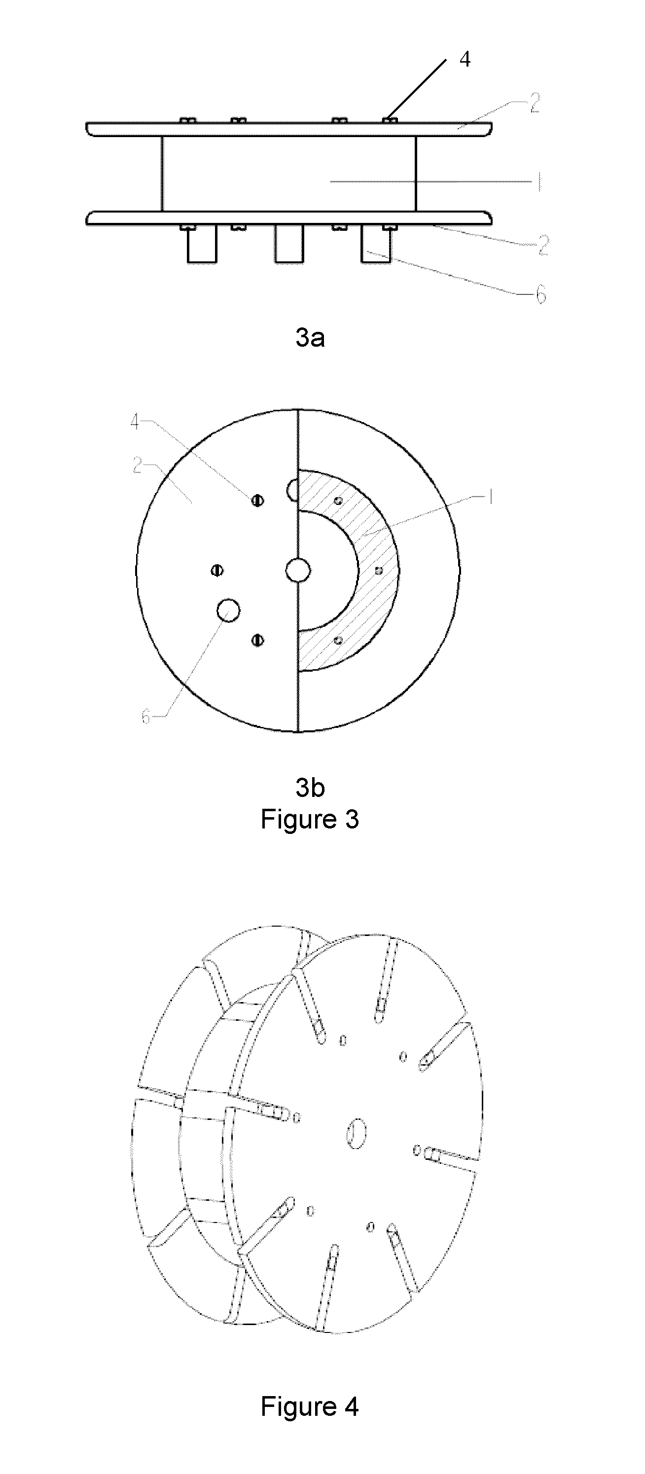
[0058]As shown, FIGS. 4, 5 and 6 are the stereogram, exploded diagrammatic drawing and sub-view of the framework of the third preferred embodiment of the detachable framework used for winding optical fiber coil in this invention, respectively. It includes a wheel hub 1, two flanges and a demountable structure. The wheel hub 1 is spliced by at least two columns whose inside and outside cylinders are curved surface. The demountable structure includes a axial through gap formed between at least one of the columns splicing places of the two facing cylinders and a filling component matching with the gap and a convex platform made on one of the ends of the wheel hub or an end of the filling component. Holes or grooves matching with the convex platform are set on the flanges. In this invention, two columns with both the inner and outer cylinders being curved surface are used, i.e., the wheel hub 1 is composed of two symmetric semi-columns. The wedged groove 5 set near the outer ring of the...


PUM


Abstract

A detachable framework used for winding optical fiber coils and a method of producing optical fiber coils with this framework. A framework with a suitable structure is designed considering comprehensively three factors, i.e., the window ratio of an optical fiber coil, the precision of an optical fiber gyro and the easy detachment of the framework from the optical fiber coil. A surface treatment with the framework is performed by coating a layer of thermosol on the surface of the framework so the optical fiber coil can be easily detached from the framework after curing. The required length of optical fiber is winded around the optical fiber coil framework, accompanying with vacuum pressure impregnating with curing adhesive after winding and optical fiber coil curing subsequently. The framework is taken off from the optical fiber coil under the heating circumstances, thereby completing production of the non-framework optical fiber coil.

Description

FIELD OF THE INVENTION[0001]This invention relates to a framework used for winding optical fiber coil and a method of producing optical fiber coil.BACKGROUND OF THE INVENTION[0002]In recent years, the domestic optical fiber gyro developed quickly. The engineering optical fiber gyro with medium and low precision was realized basically and was used successfully in many fields; the research and manufacture of the high-precision optical fiber gyro also went ahead like a raging fire. But generally speaking, there is a great gap between the domestic and foreign level. According to the basic working principle of optical fiber gyro:ΔϕR=2πLDλCΩ(1)[0003]In which, ΔφR is the phase difference between two beams of light which propagates in opposite directions in optical fiber coil, L is length of the optical fiber coil, D is the average diameter of the optical fiber coil, λ is the wave length of light wave, C is the propagation speed of light wave in vacuum, Ω is the angle speed to which the opt...

Claims


Application Information

Patent Timeline
Patent Type & Authority Applications(United States)
IPC IPC(8): B05D5/06B65H75/14B65H75/22B65H59/00
CPCG01C19/722
Inventor WANG, WEILI, JINGYANG, QINGSHENGWANG, XUEFENGTAN, JINQUAN
Owner BEIJING AEROSPACE TIMES OPTICAL ELECTRONICS TECH
Why Eureka
Try Eureka