Optical disk drive

a technology of optical disk drives and locking mechanisms, which is applied in the direction of data recording, instruments, information storage, etc., can solve the problems of limited control of the motion space of the tray, difficult to achieve a stable lock operation with a small thickness and a small number of components, and difficult to fully avoid the failure of the engagement between the tray and the chassis. to achieve the effect of preventing an engaging failure in the lock operation of the optical disk drive and achieving a stable lock operation

Inactive Publication Date: 2010-10-14
HITACHI-LG DATA STORAGE
View PDF8 Cites 6 Cited by
  • Summary
  • Abstract
  • Description
  • Claims
  • Application Information

AI Technical Summary

Benefits of technology

[0017]According to the present invention, it is possible to prevent an engaging failure in the lock operation of the optical disk drive and to perform a stable lock operation.

Problems solved by technology

However, the effect of controlling the motion space of the tray is limited to a back portion of the tray (the back direction than the rotation center of a spindle motor) in the near field region of the projecting portion.
For this reason, it would be difficult to fully avoid the failure of the engagement between the tray and the chassis.
For this reason, it would be difficult to achieve a stable lock operation with a small thickness and a small number of components as in the case of the notebook personal computer.

Method used


Image

  • Optical disk drive
  • Optical disk drive
  • Optical disk drive

Examples


Embodiment Construction

[0028]Hereinafter, an embodiment of the present invention will be described with reference to the accompanying drawings.

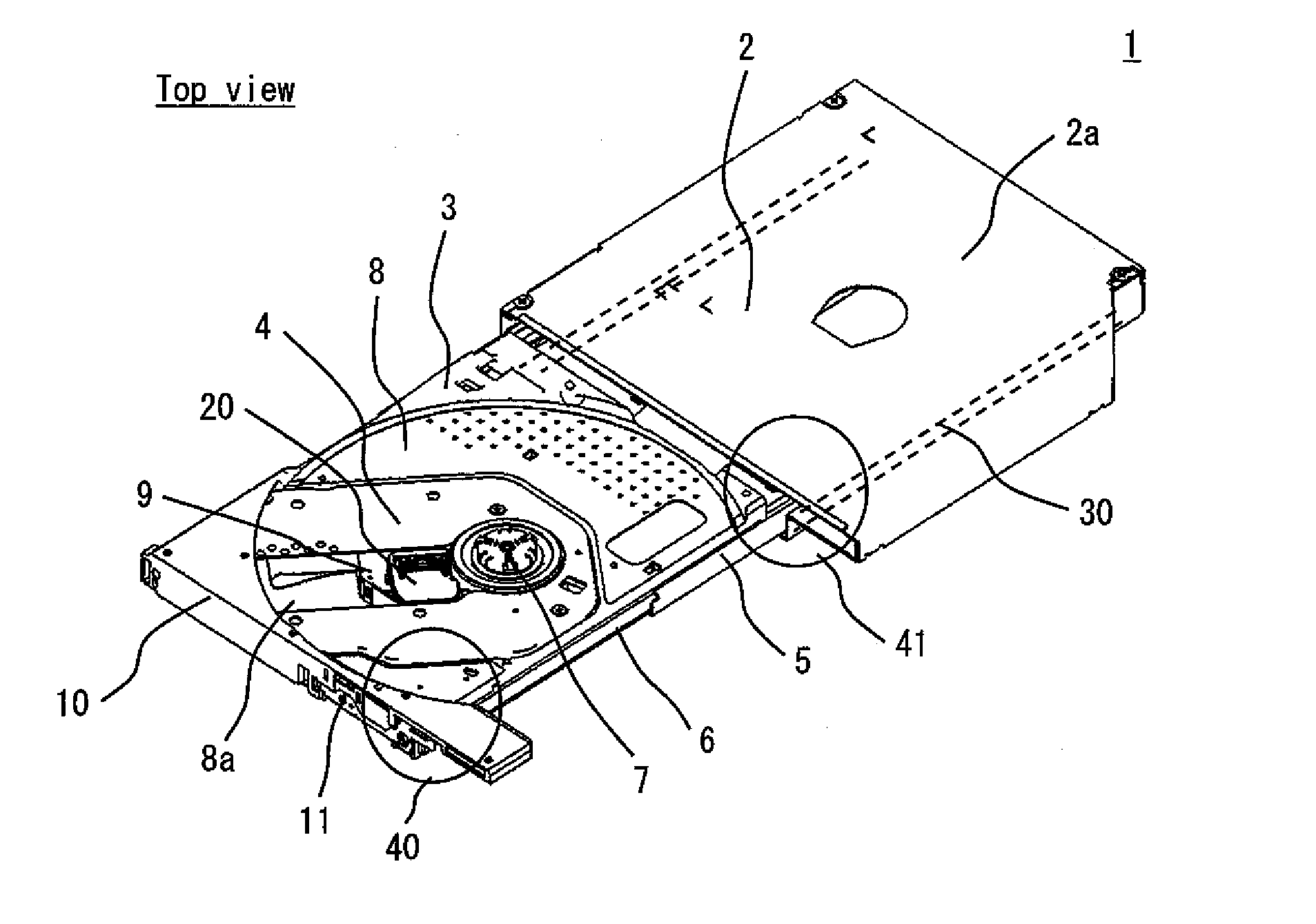
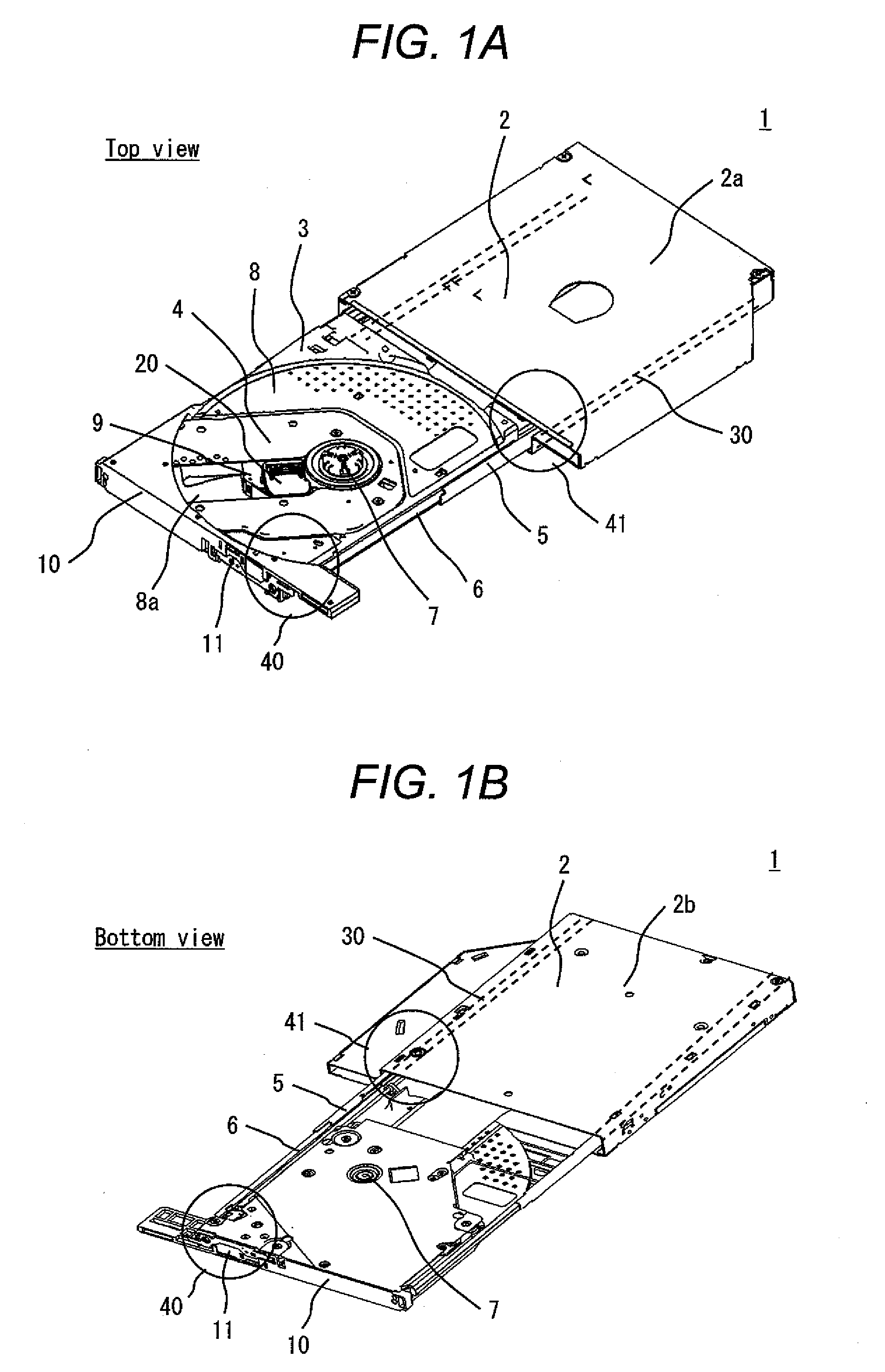
[0029]FIGS. 1A and 1B are external views of an optical disk drive according to an embodiment of the present invention. FIG. 1A is a perspective view seen from the top side of the optical disk drive, and FIG. 1B is a perspective view seen from the back side thereof. In FIGS. 1A and 1B, reference numeral 1 denotes an optical disk drive, reference numeral 2 denotes a chassis, reference numeral 2a denotes an upper chassis portion, reference numeral 2b denotes a lower chassis portion, reference numeral 3 denotes a tray, reference numeral 4 denotes an optical pickup module, reference numeral 5 denotes a rail, reference numeral 6 denotes a rail holding portion, reference numeral 7 denotes a spindle motor, reference numeral 8 denotes a cover, reference numeral 8a denotes an opening, reference numeral 8b denotes a back cover, reference numeral 9 denotes a carriage, referenc...


PUM

PropertyMeasurementUnit
timeaaaaaaaaaa
thicknessaaaaaaaaaa
movementaaaaaaaaaa

Abstract

The present invention provides an optical disk drive that performs a stable lock operation with a small number of components at the time of the insertion of a tray. The optical disk drive has a locking mechanism which engages the inserted tray with the chassis, a reset arm provided in the tray to return the locking mechanism to the initial state, and an engaging boss that is provided in the chassis and is engaged with the reset arm. The tray has a projecting portion for controlling the engagement position between the reset arm and the engaging boss. The projecting portion comes into contact with a back surface of the engaging boss, to control the engaging amount between the reset arm and the engaging boss to be constant.

Description

CLAIM OF PRIORITY[0001]The present application claims priority from Japanese patent application serial No. JP 2009-094941, filed on Apr. 9, 2009, the content of which is hereby incorporated by reference into this application.BACKGROUND OF THE INVENTION[0002](1) Field of the Invention[0003]The present invention relates to an optical disk drive for recording and reproducing information with respect to an optical disk. More specifically, the present invention relates to a locking mechanism used when a tray on which an optical disk is placed is inserted into a chassis.[0004](2) Description of the Related Art[0005]In general, an optical disk drive installed in an electronic device has a tray held in a drive body (chassis) so that the tray is automatically inserted into and ejected from the drive body or the chassis. The tray is ejected from the chassis to place an optical disk thereon, and is inserted into the chassis again. In this way, the optical disk is loaded into the drive body. Th...

Claims


Application Information

Patent Timeline
Patent Type & Authority Applications(United States)
IPC IPC(8): G11B17/04
CPCG11B17/056
Inventor MATSUMOTO, KOJIHAMAIE, SEIJIISHIZUKA, YOSUKE
Owner HITACHI-LG DATA STORAGE
Why Eureka
Try Eureka