Electric motor control device and electric motor control method

a technology of electric motors and control devices, which is applied in the direction of motor/generator/converter stoppers, dynamo-electric gear control, dynamo-electric converter control, etc., can solve the problems of increasing cost, increasing computation load, increasing computation load, etc., and achieving increased computation load, increased control performance, and increased computation load

Active Publication Date: 2015-03-05
NISSAN MOTOR CO LTD
View PDF3 Cites 7 Cited by
  • Summary
  • Abstract
  • Description
  • Claims
  • Application Information

AI Technical Summary

Benefits of technology

[0004]However, in the technique disclosed in JP 2007-159368A, a torque feedback loop is added to the current control mode, so that a computation load increases. Although the increase of the computation load may be alleviated by setting the computation period to be longer, control performance inevitably decreases. In addition, a higher performance computation device may be employed. However, this may increase cost.
[0005]In view of the aforementioned problems, the present invention has an object to provide a technology for reducing a computation load to suppress a torque discontinuity at the time of control mode switching.

Problems solved by technology

However, in the technique disclosed in JP 2007-159368A, a torque feedback loop is added to the current control mode, so that a computation load increases.
Although the increase of the computation load may be alleviated by setting the computation period to be longer, control performance inevitably decreases.
However, this may increase cost.

Method used


Image

  • Electric motor control device and electric motor control method
  • Electric motor control device and electric motor control method
  • Electric motor control device and electric motor control method

Examples


first embodiment

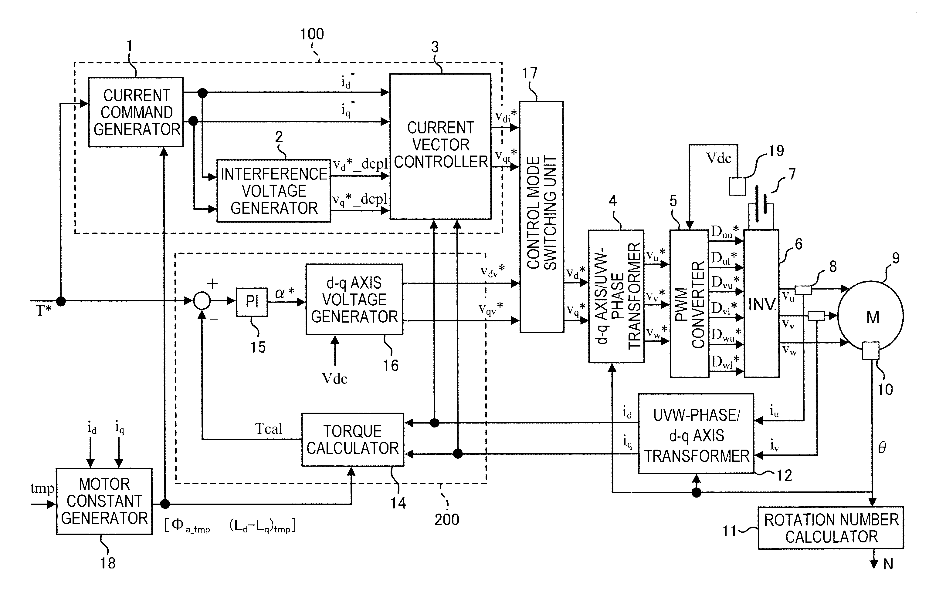
[0014]FIG. 1 is a control block diagram illustrating an electric motor control according to a first embodiment. This control is executed based on a flowchart described below.

[0015]The control according to the first embodiment is performed by switching between a current control mode and a voltage phase control mode depending on a driving state of an electric motor. The current control mode is a control mode performed to match a current command value based on a torque command value and a motor constant corresponding to a magnet temperature of an electric motor 9. The voltage phase control mode is a control mode in which a torque feedback operation is performed for a voltage phase based on a difference between a torque command value and a torque estimation value obtained from a torque computation formula. In addition, the mode switches to the voltage phase control mode in a high rotation area where a flux weakening control is performed.

[0016]A current control unit 100 in FIG. 1 include...

second embodiment

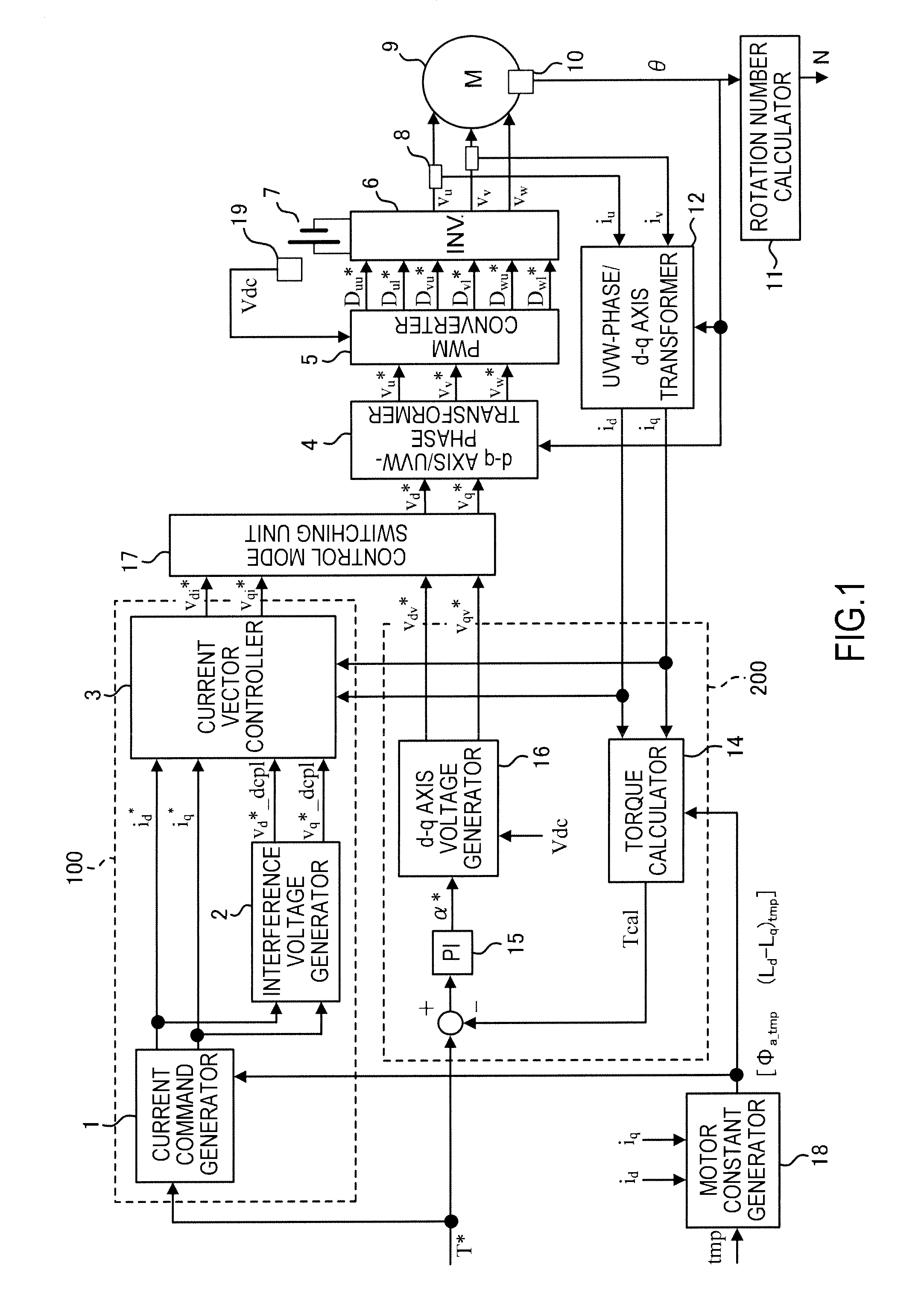
[0039]FIG. 2 is a control block diagram illustrating an electric motor control according to a second embodiment. This control is executed based on the flowchart described below.

[0040]According to the second embodiment, the magnet temperature tmp is set to a fixed value (25° C.), and an inductance generator 13 is provided instead of the motor constant generator 18. As a result, the computation performed in the current control unit 100 and the voltage phase control unit 200 is different from that of the first embodiment. Hereinafter, a description will focus on a difference from the first embodiment. It is noted that the temperature “25° C.” is set based on a performance guarantee temperature or an ambient temperature of an operational environment in order to fix the magnet temperature tmp, and the invention is not limited thereto.

[0041]A description will now be made for the current control unit 100.

[0042]The current command generator 1 receives the torque command value T*, the rotati...

third embodiment

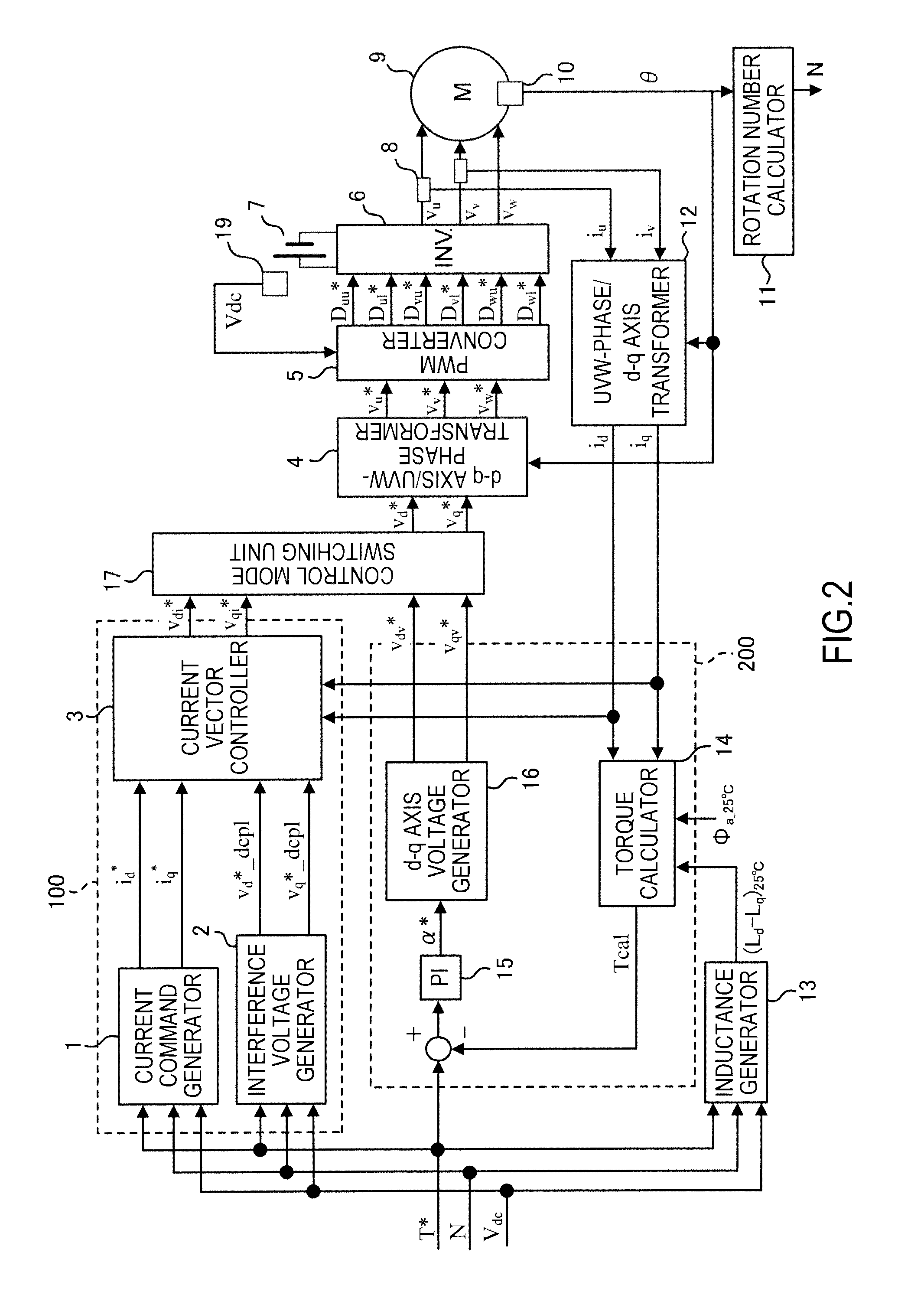
[0049]FIG. 3 is a control block diagram illustrating an electric motor control according to a third embodiment. This control is executed based on the flowchart described below.

[0050]Hereinafter, a description will focus on a difference from the second embodiment.

[0051]The current command generator 1 and the interference voltage generator 2 receive the torque command value T*, the rotation speed N, and the battery voltage Vdc and generates and outputs the d-q axis current command values id* and iq* and the d-q axis interference voltage values vd—dcpl, vq*—dcpl at tmp=25° C. by referring to a table created in advance through experiment or computation. It is noted that, as a pre-requisite of the table creation, a modulation rate M* in a saturation area of the motor application voltage, that is, in a flux weakening area is equally set to the modulation rate M* used when the d-q axis voltage generator 16 calculates the d-q axis voltage command values vdv* and vqv* for the voltage phase c...


PUM


Abstract

An electric motor control device includes: a motor constant generator configured to generate a motor constant by using a temperature; a current control unit configured to generate a current command value to an electric motor based on the motor constant and a torque command value and execute a current control mode; a voltage phase control unit configured to calculate a torque estimation value of the electric motor and execute a voltage phase control mode in which a feedback operation is performed for a voltage phase based on the difference between the torque estimation value and the torque command value; and a control mode switching unit configured to switch to the voltage phase control mode in a high rotation area where a flux weakening control is performed. The torque estimation value is calculated using the motor constant common to generation of the current command value in the current control mode.

Description

TECHNICAL FIELD[0001]The present invention relates to a control of a system where a DC voltage supplied from a battery is converted into an AC voltage using an inverter and the AC voltage is applied to an AC motor.BACKGROUND ART[0002]As a method of controlling a torque of an alternating current (AC) electric motor, there are known an electric current control method and a voltage control method. As the electric current control method, for example, there is known a pulse width modulation (PWM) control in which an electric current is controlled based on a vector control. As the voltage control method, there is known a rectangular wave control in which rotation of the AC electric motor is driven by applying a rectangular wave voltage. In addition, as a control for improving an output power in a so-called flux weakening area, there is known a voltage phase control in which a torque of the AC electric motor is controlled by controlling a voltage phase depending on a difference between a t...

Claims


Application Information

Patent Timeline
Patent Type & Authority Applications(United States)
IPC IPC(8): H02P6/08H02P21/05H02P21/00H02P21/14H02P21/16H02P21/18H02P21/22H02P21/24H02P23/04H02P23/14H02P23/28H02P27/04H02P27/08
CPCH02P6/08H02P21/0089H02P21/16H02P21/20H02P29/662
Inventor SHOUJI, MITSUHIRO
Owner NISSAN MOTOR CO LTD
Why Eureka
Try Eureka