Vehicle control system

a technology of vehicle control and control system, which is applied in the direction of control devices, driver input parameters, vehicle components, etc., can solve the problems of unsteady movement of the vehicle, vehicle travel caused by the automated turning control not necessarily matching the driver's feeling, and the vehicle does not travel as desired by the driver, so as to reduce the sense of strangeness and annoyance of the driver during the execution of the automated turning control

Active Publication Date: 2020-08-20
TOYOTA JIDOSHA KK
View PDF0 Cites 5 Cited by
  • Summary
  • Abstract
  • Description
  • Claims
  • Application Information

AI Technical Summary

Benefits of technology

[0005]An object of the present disclosure is to provide a technique that can reduce the driver's senses of strangeness and annoyance during execution of the automated turning control.
[0018]In the system suppression processing, the control device decreases a control gain used for calculating a control amount of the automated turning control as compared to the case where the modification desire degree is equal to or lower than the threshold.
[0047]The vehicle control system according to the present disclosure executes the system suppression processing when the modification desire degree exceeds the threshold during execution of the automated turning control. In the system suppression processing, the vehicle control system weakens the automated turning control as compared to the case where the modification desire degree is equal to or lower than the threshold. As a result, the driver's senses of strangeness and annoyance during execution of the automated turning control are reduced.
[0048]Moreover, the vehicle control system calculates the modification desire degree that represents a degree to which the steering operation performed by the driver modifies vehicle travel caused by the automated turning control. Then, the vehicle control system determines whether to execute the system suppression processing based on the calculated modification desire degree. The driver's feeling varies from driver to driver. In addition, even for a same driver, the driver's desire can vary depending on a situation. That is, the driver's desire can vary in drivers and depending on a situation. Not merely detecting the driver's steering operation but also specifically calculating and referring to the modification desire degree makes it possible to appropriately grasp the driver's desire.

Problems solved by technology

Vehicle travel caused by the automated turning control does not necessarily match driver's feeling (intention, preference).
Such the modification by the driver is disturbance for the automated turning control.
This causes unsteady motion of the vehicle.
In addition, the vehicle does not travel as desired by the driver.
As a result, the driver feels senses of strangeness and annoyance.

Method used


Image

  • Vehicle control system
  • Vehicle control system
  • Vehicle control system

Examples


first embodiment

1. First Embodiment

1-1. Outline

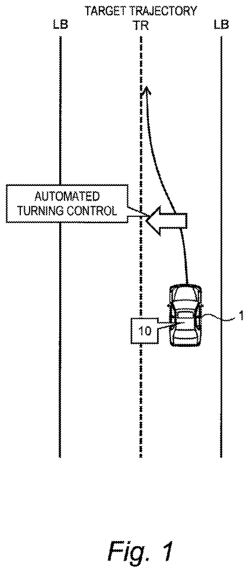
[0064]FIG. 1 is a conceptual diagram for explaining an outline of a vehicle control system 10 according to a first embodiment. The vehicle control system 10 is installed on a vehicle 1 and controls the vehicle 1. In particular, the vehicle control system 10 at least executes “automated turning control” that automatically turns (i.e. changes a direction of) a wheel of the vehicle 1.

[0065]An example of the automated turning control is trajectory-following control. The vehicle control system 10 determines a target trajectory TR and controls travel (at least one of turning, acceleration, and deceleration) of the vehicle 1 such that the vehicle 1 follows the target trajectory TR. Such the trajectory-following control is executed in automated driving control, lane tracing assist (LTA), and the like.

[0066]Another example of the automated turning control is lane departure prevention control that prevents the vehicle 1 from departing from a travel lane. For exa...

second embodiment

2. Second Embodiment

[0131]A second embodiment differs from the above-described first embodiment in the system suppression processing (Step S400). An overlapping description with the first embodiment will be omitted as appropriate.

[0132]FIG. 12 is a block diagram showing a functional configuration related to the system suppression processing according to the second embodiment. The system suppression processing unit 140 strengthens the driver-driven turning control executed by the driver-driven turning control unit 110 instead of weakening the automated turning control executed by the automated turning control unit 120.

[0133]In particular, the system suppression processing unit 140 strengthens the assist control executed by the assist control unit 111 (see FIG. 8). Here, “strengthening the assist control” means increasing influence (contribution) of the assist control on the turning of the wheel 2. As described above, the assist control unit 111 calculates the basic assist control amo...

third embodiment

3. Third Embodiment

[0135]In a third embodiment, a vehicle 1 of a steer-by-wire type is considered. An overlapping description with the first embodiment will be omitted as appropriate.

[0136]FIG. 13 is a block diagram showing a configuration example of the vehicle 1 and the vehicle control system 10 according to the third embodiment. The wheel 2 and the steering wheel 3 (the steering shaft 4) can be mechanically separated from each other. The vehicle control system 10 further includes a reaction torque generation device 30 in addition to the configuration described in the first embodiment (see FIG. 5).

[0137]The reaction torque generation device 30 applies a reaction torque to the steering wheel 3 in a pseudo manner. More specifically, the reaction torque generation device 30 includes a reaction motor (a reaction actuator). A rotor of the reaction motor is connected to the steering shaft 4 through a speed reducer. Actuating the reaction motor makes it possible to apply the reaction tor...


PUM


Abstract

A vehicle control system includes: a turning device that turns a wheel of a vehicle; a steering sensor that detects a driver's steering operation; and a control device configured to execute automated turning control that controls the turning device to automatically turn the wheel, independently of the driver's steering operation. A modification desire degree represents a degree to which the driver's steering operation modifies vehicle travel caused by the automated turning control. During execution of the automated turning control, the control device calculates the modification desire degree based on a result of detection by the steering sensor. When the modification desire degree exceeds a threshold, the control device executes system suppression processing without terminating the automated turning control. In the system suppression processing, the control device weakens the automated turning control as compared to a case where the modification desire degree is equal to or lower than the threshold.

Description

BACKGROUNDTechnical Field[0001]The present disclosure relates to a vehicle control system installed on a vehicle. In particular, the present disclosure relates to a vehicle control system that executes automated turning control.Background Art[0002]Patent Literature 1 discloses a steering assist device of a vehicle. The steering assist device performs steering assist for a driver by applying a steering torque to a steering system such that the vehicle travels along a lane.LIST OF RELATED ART[0003]Patent Literature 1: Japanese Laid-Open Patent Application Publication No. JP-2014-024448SUMMARY[0004]Let us consider “automated turning control” that automatically turns (i.e. changes a direction of) a wheel of a vehicle. Vehicle travel caused by the automated turning control does not necessarily match driver's feeling (intention, preference). Therefore, during execution of the automated turning control, the driver may perform a steering operation (i.e. an operation of a steering wheel) to ...

Claims


Application Information

Patent Timeline
Patent Type & Authority Applications(United States)
IPC IPC(8): B62D15/02B60W50/10B62D6/10
CPCB60W50/10B62D6/10B62D15/026B60W2510/202B62D15/021B60W2540/18B62D6/00B60W30/12B60W10/20B60W40/02B60W2520/10B60W2520/105B60W2520/28B62D15/025B60W2710/207B60W2050/0008B60W2050/0024
Inventor SATO, MASAYAKUNIHIRO, YOJIWATANABE, YOSHINORITANIMORI, SHUNSUKEAKATSUKA, HISAYA
Owner TOYOTA JIDOSHA KK
Why Eureka
Try Eureka