Battery Forklift Truck

a battery-powered forklift and forklift technology, which is applied in the direction of positive displacement liquid engine, piston pump, fluid coupling, etc., can solve the problems of poor maintainability of dc motor, low efficiency, low efficiency, etc., and achieve the effect of small size, reduced size and increased torque of load-handling motor composed of permanent magnet type synchronous motor

Inactive Publication Date: 2007-09-20
MITSUBISHI HEAVY IND LTD
View PDF5 Cites 7 Cited by
  • Summary
  • Abstract
  • Description
  • Claims
  • Application Information

AI Technical Summary

Benefits of technology

[0011] The present invention was made in light of the problems mentioned above, and the object of the invention is to provide a battery forklift truck installed with a permanent magnet type synchronous motor, in which the necessity of field weakening control of the permanent magnet type synchronous motor is eliminated and motor efficiency when performing load handling and steering is increased.

Problems solved by technology

However, DC motors are not good in maintainability and low in efficiency resulting in earlier battery drain and induction motors are low in efficiency resulting in earlier battery drain.
However, when performing the field weakening control in high rotation speed range of the motor, since a current is passed which does not contribute to motor torque, copper loss increases resulting in decreased efficiency of the motor.
As a result, efficiency of the motor decreases in the range of high rotation speed caused by field weakening control in the high rotation speed range of the motor.

Method used


Image

  • Battery Forklift Truck
  • Battery Forklift Truck
  • Battery Forklift Truck

Examples


first embodiment

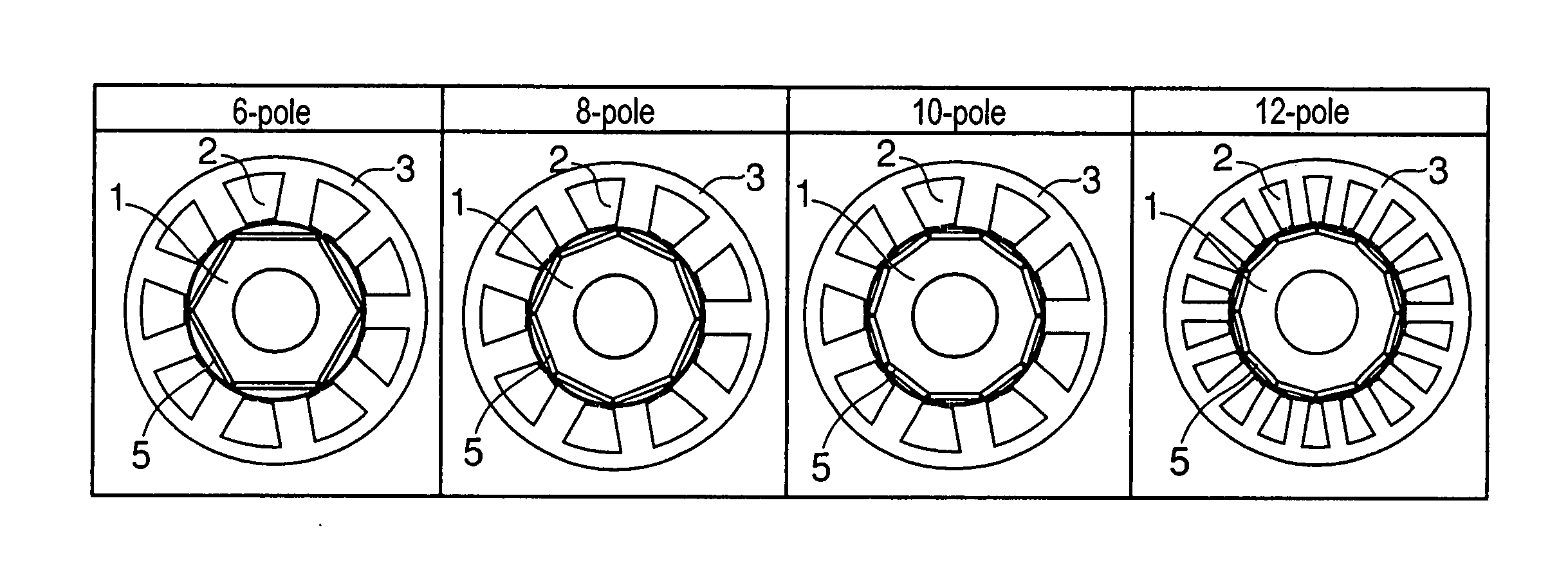
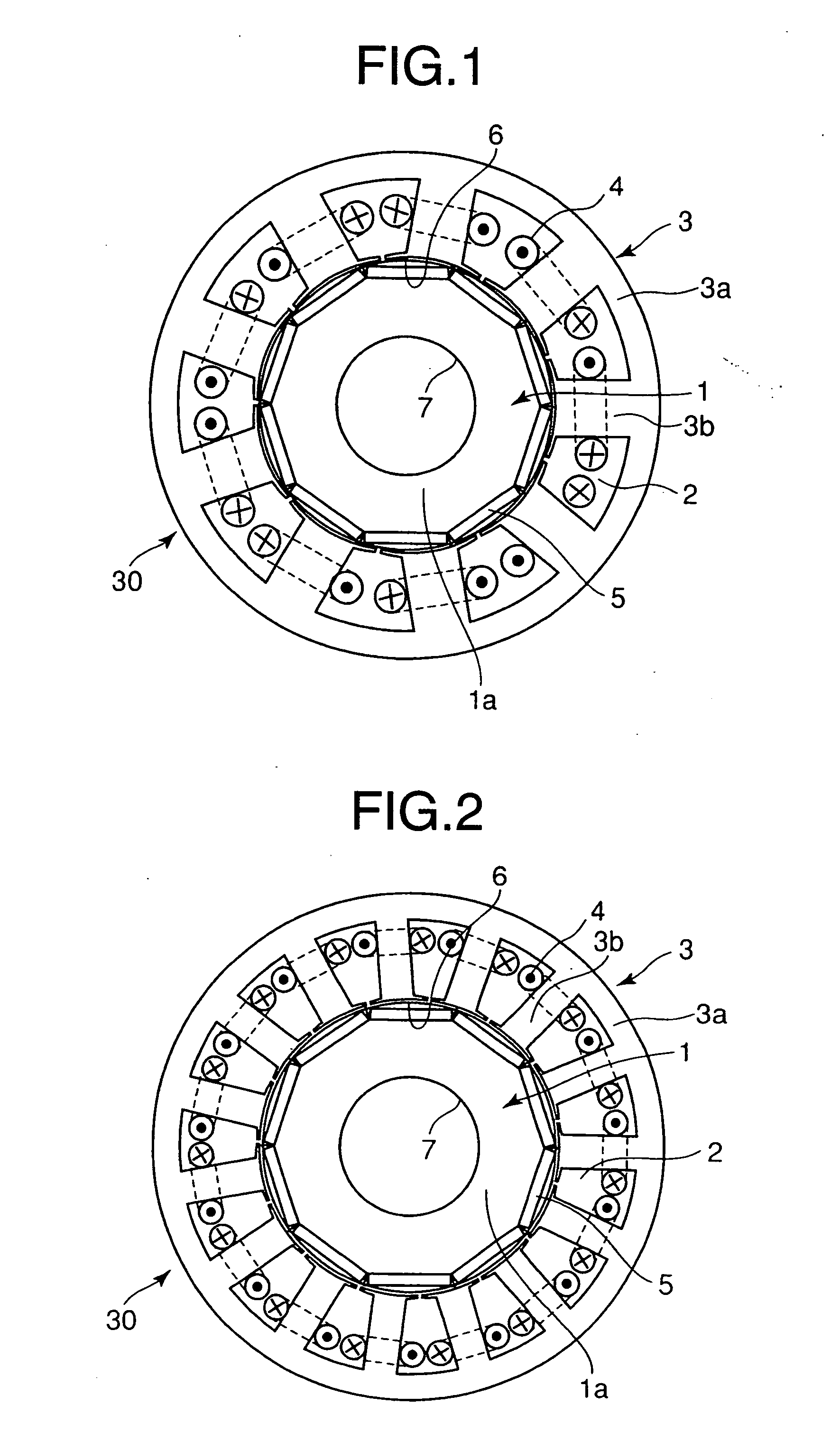
[0045]FIG. 1 is a schematic sectional view perpendicular to the rotation axis of the permanent magnet type synchronous motor of a first embodiment for the battery forklift truck of the present invention, showing the construction of the rotor and stator.

[0046] In FIG. 1, reference numeral 1 is a rotor, 1a is an iron core of the rotor 1, 7 is a bore provided in the iron core into which a rotation shaft (not shown in the drawing) for driving the oil hydraulic pump 33 being fitted to be connected to the iron core.

[0047] Reference numerals 5 are a plurality of permanent magnets embedded in the rotor, each of the magnets 5 being a flat plate.

[0048] These magnet plates are arranged on the outer periphery of the rotor such that they are disposed at a certain interval along circumferential direction of the rotor 1 so that the outside surface of each magnet plate comes close to the outer circumferential surface 6 of the rotor 1. It is also suitable that the permanent magnets are plates of ...

second embodiment

[0053]FIG. 2 is a view as in FIG. 1 of a second embodiment of the present invention.

[0054] In the second embodiment, the number of the permanent magnets 5 embedded in the rotor is 10, i.e. the number of poles is 10 as is in the first embodiment, and the number of slots 2 is 15 (i.e. the number of the tooth parts 3b of the stator is 15).

[0055] Construction other than that is identical to the first embodiment, and constituent parts same as those of the first embodiment are denoted by the same reference numerals respectively.

third embodiment

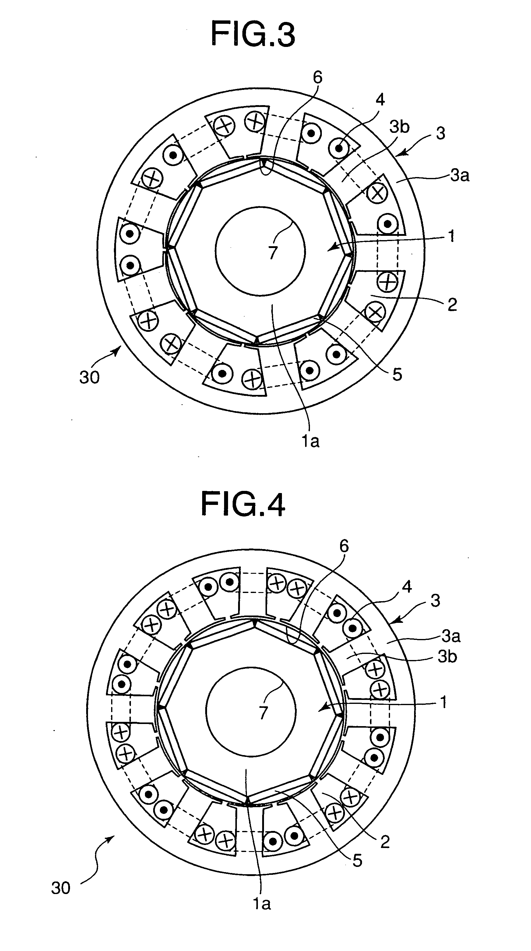
[0056]FIG. 3 is a view as in FIG. 1 of a third embodiment of the present invention.

[0057] In the third embodiment, the number of the permanent magnets 5 embedded in the rotor is 8, i.e. the number of poles is 8, and the number of slots 2 is 9 (i.e. the number of the tooth parts 3b of the stator is 9).

[0058] Construction other than that is identical to the first embodiment, and constituent parts same as those of the first embodiment are denoted by the same reference numerals respectively.


PUM


Abstract

A battery forklift truck using a permanent magnet type synchronous motor, wherein the permanent magnet type synchronous motor for load handling is installed separately from a traveling motor driving wheels. The maximum rotational speed of the motor for load handling is set lower than that of the traveling motor to eliminate the need of field weakening control in a high rotational speed range so that the efficiency of the motor in load handling can be increased.

Description

TECHNICAL FIELD [0001] The present invention relates to a battery forklift truck in which a permanent magnet type motor is used for load handling, the permanent magnet type motor comprising a stator having coils inserted in a plurality of slots in the stator and a rotor having a plurality of permanent magnets arranged on the outer periphery of the rotor along the circumferential direction in a state they are embedded therein. BACKGROUND ART [0002] In recent years, energy-saving, low-emission battery forklift trucks are more prevalent than engine-driven forklift trucks. [0003] DC motors, induction motors, and permanent magnet type synchronous motors as disclosed in Japanese Laid-Open Patent Application No. 2002-165428 are adopted for driving battery forklift trucks. However, DC motors are not good in maintainability and low in efficiency resulting in earlier battery drain and induction motors are low in efficiency resulting in earlier battery drain. Therefore, as driving machines of ...

Claims


Application Information

Patent Timeline
Patent Type & Authority Applications(United States)
IPC IPC(8): F04B35/04F15B7/00
CPCB60L1/003B60L2220/14B66F9/07531B66F9/07572Y02T10/7258H02K1/278H02K21/16Y02T10/641B66F9/24Y02T10/64Y02T10/72
Inventor ISOBE, SHINICHISAKURAI, TAKAOENOMOTO, KIYOSHISHIRASU, TAKAYAMORIMOTO, MASAYUKI
Owner MITSUBISHI HEAVY IND LTD
Why Eureka
Try Eureka