Mike 4001 design of the stator of electrical motor & generator

a stator and electrical motor technology, applied in the direction of magnetic circuit rotating parts, magnetic circuit shape/form/construction, transportation and packaging, etc., can solve the problems of less efficiency of electrical motors and energy loss in creating magnetic flux, and achieve the effects of improving efficiency, extending volume, and motors more efficien

Inactive Publication Date: 2005-10-13
CHEN YUE CHUNG
View PDF11 Cites 0 Cited by
  • Summary
  • Abstract
  • Description
  • Claims
  • Application Information

AI Technical Summary

Benefits of technology

[0012] The way I develop to make motor more efficient is to design a different motor stator structure to keep the magnetic flux pattern the same as before and to let electrical wire get as close contact as possible to the part of the stator structure where we want the magnetic flux be generated. Because the magnetic flux pattern is the same as before so the motor will function just as before. The new shape of stator structure which gets extended volume to cover the space where electrical winding originally is. The extended stator part gets holes through to accommodate the electrical windings, so the position and formation of electrical windings will stay unchanged then the magnetic flux pattern in the stator will not be changed. The motor (or generator) will function as before but with its efficiency improved.

Problems solved by technology

This will cause energy loss in creating magnetic flux in stator and make electrical motor less efficiency.

Method used


Image

  • Mike 4001 design of the stator of electrical motor & generator
  • Mike 4001 design of the stator of electrical motor & generator
  • Mike 4001 design of the stator of electrical motor & generator

Examples


Embodiment Construction

[0030] How to build the structure (mike 4001):

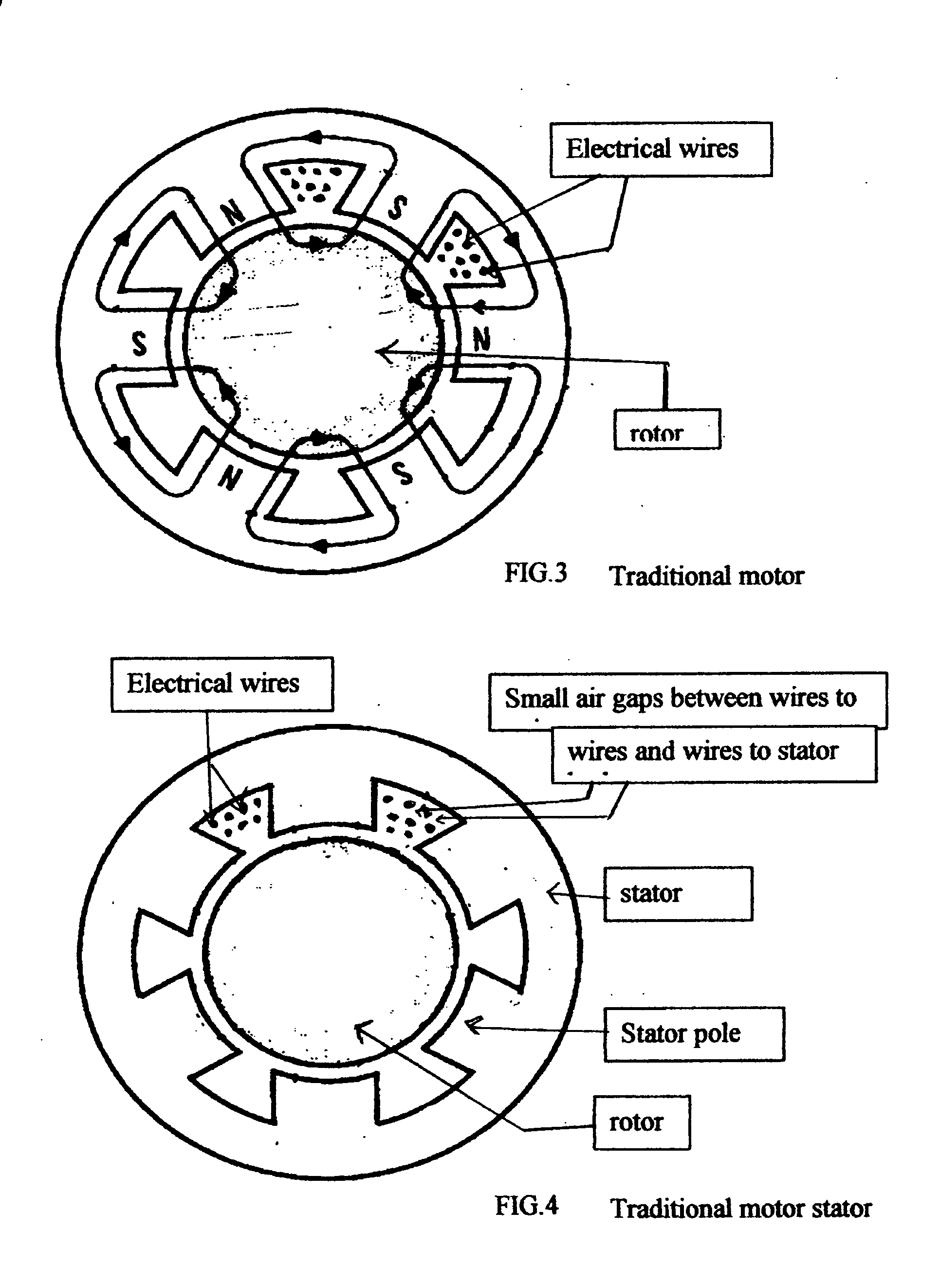
[0031] First: we can build a stator (like FIG. 4-a);

[0032] Second: we drill holes in the position where the electrical wires used to be (FIG. 4-b).

[0033] Third: we insert insulated painted electrical wire into those holes (FIG. 4-c).

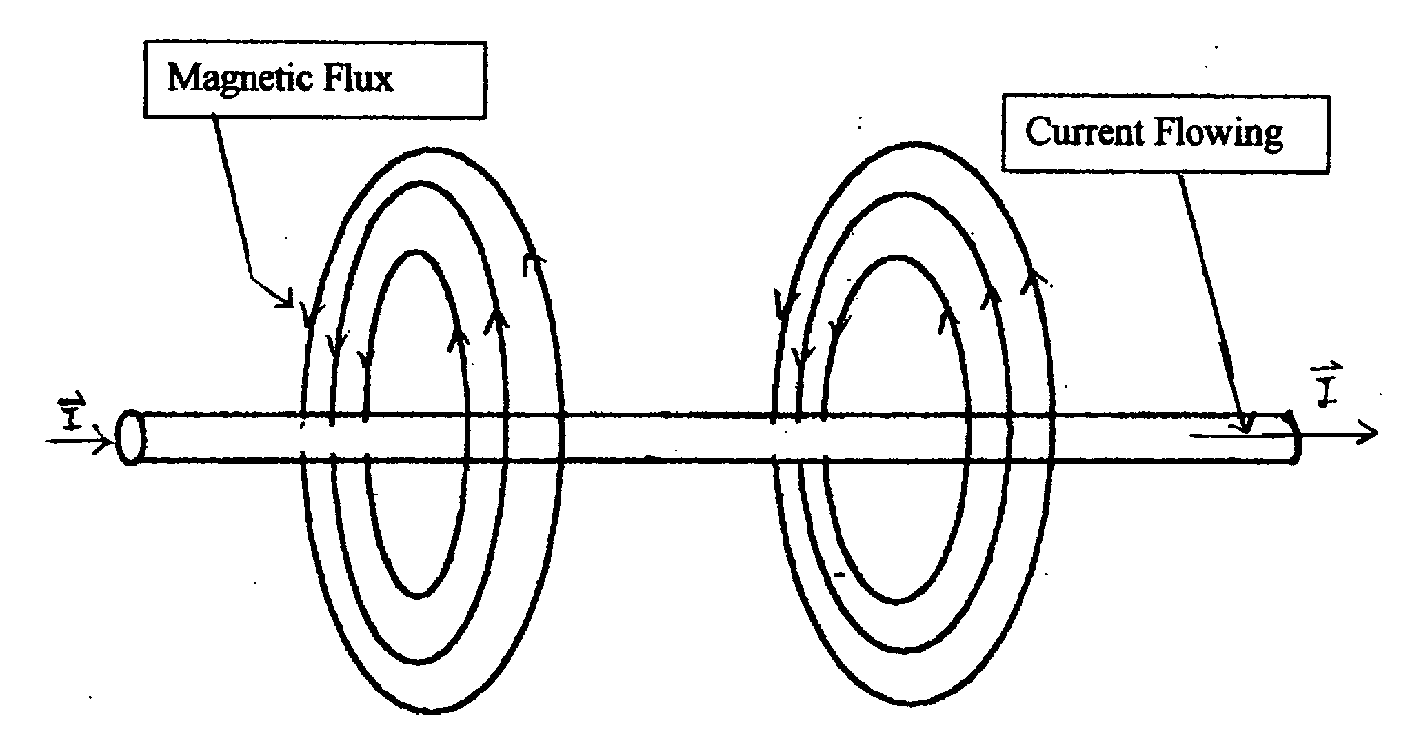
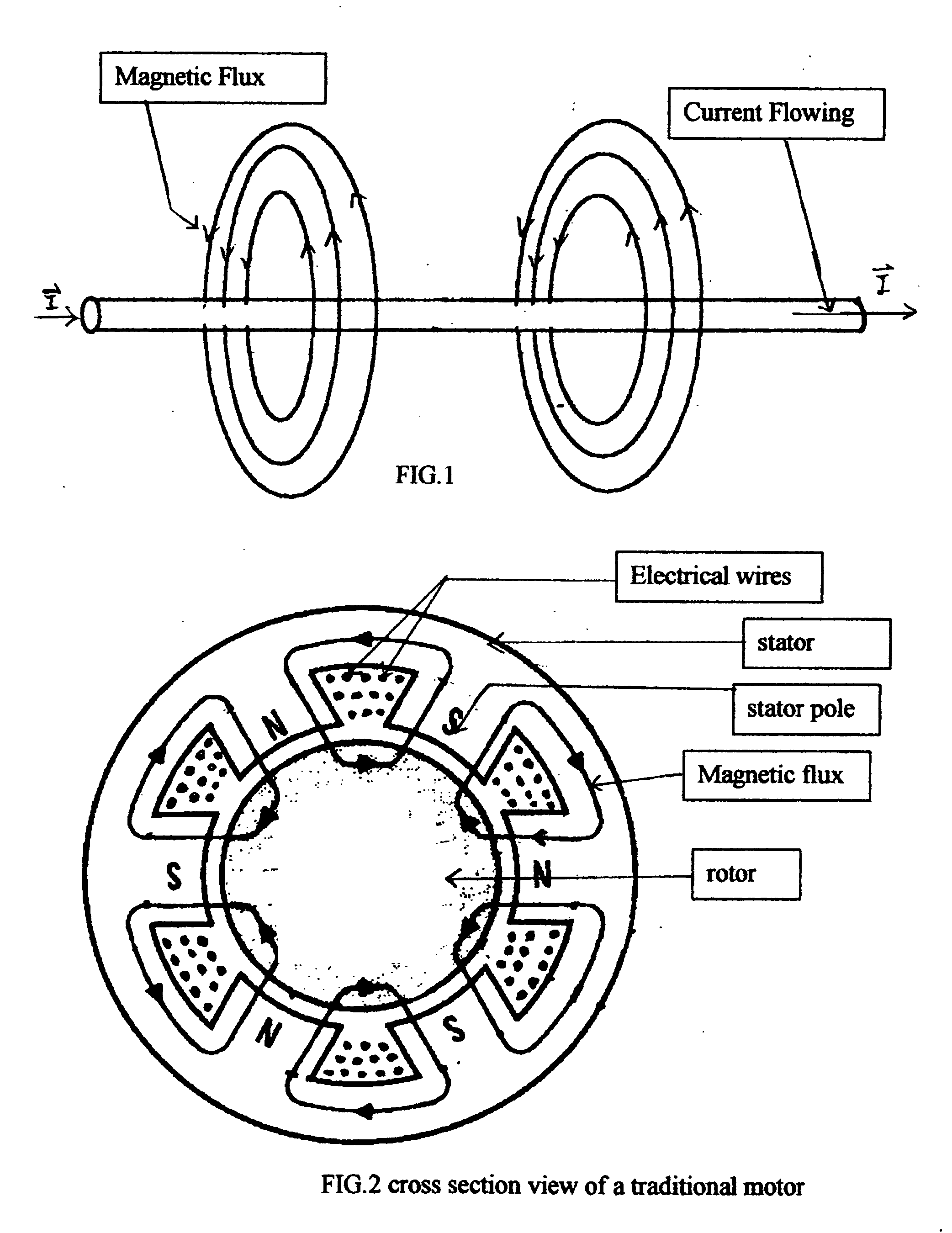
[0034] The magnetic flux (FIG. 4-1) will flow like those in the traditional motor (FIG. 2) but both stator structures are not the same. The new design (mike 4001) consumes much less current due to much less air gap the magnetic fluxes need to overcome to reach the stator structure.

[0035] The new design of stator (mike 4001) will look like FIG. 411. With different electrical winding, it may look like FIG. 4-2 (mike 4002), FIG. 4-3 (mike 4003). The whole stator is in different shape from a traditional one and the material is soft magnetic material just as the traditional one. It is also a laminated structure to reduce eddy current. Electrical wires are insulated painted and inserted into holes, which are d...


PUM

PropertyMeasurementUnit
volumeaaaaaaaaaa
magnetic fluxaaaaaaaaaa
magnetomotive forceaaaaaaaaaa

Abstract

When we use a new structure of stator of a motor (or generator) to let magnetic flux travel less distance in air and keep the flux pattern the same as before then we can improve its efficiency. Motor structure didn't change too much in decades. If we can greatly improve its efficiency and along with battery capacity, lessen their weight, then an electrical car may be as practical as a gasoline car. The electrical airplane may also become practical. The power plant may generate more electricity with same energy consumed.

Description

CROSS REFERENCE TO RELATED APPLICATION U.S. Patenet Documents [0001]U.S. Pat. No. 4,146,210March 1979Koval et al.254 / 375U.S. Pat. No. 5,295,194March 1994Christensen,381 / 190Eugene J.U.S. Pat. No. 6,326,713December 2001Judson, John310 / 112STATEMENT REGARDING FEDERALLY SPONSORED RESEARCH OF DEVELOPMENT [0002] not applicable REFERENCE OT SEQUENCE LISTING, A TABLE, OR A COMPUTER PROGRAM LISTING COMPACT DISK APPENDIX [0003] not applicable BACKGROUND OF INVENTION [0004] Textbook definition of “magnetic saturation condition”: the maximum magnetic flux in a material, it can't be increased significantly even with a higher magnetomotive force applied. [0005] Textbook definition of “soft magnetic material”: the soft magnetic materials show magnetic properties only when they are subject to a magnetizing force. [0006] In order to increase the efficiency of an electrical motor, we need to maintain the same strength of the magnetic filed (close to but below the magnetic saturation condition) in the ...

Claims


Application Information

Patent Timeline
Patent Type & Authority Applications(United States)
IPC IPC(8): H02K1/00H02K1/22H01F27/34H01F27/30H01F27/245H02K1/12H02K3/04
CPCH01F27/245H01F27/306H01F27/34H02K1/12H02K1/22Y02T10/641Y02T10/64
Inventor CHEN, YUE-CHUNG
Owner CHEN YUE CHUNG
Why Eureka
Try Eureka