Coil insertion method and coil insertion device

a coil and insertion method technology, applied in the direction of dynamo-electric machines, electrical apparatus, manufacturing dynamo-electric machines, etc., can solve the problems of easy deformation of the radial plate positioned between the holding grooves of the jig, and achieve the effect of reducing the length of the coil, reducing the risk of deformation, and improving the efficiency of the motor

Active Publication Date: 2022-08-09
KATO YOSHIO
View PDF15 Cites 0 Cited by
  • Summary
  • Abstract
  • Description
  • Claims
  • Application Information

AI Technical Summary

Benefits of technology

[0004]Therefore, an object of the present invention is to provide a coil insertion method and device that are capable of mechanically manufacturing, with good efficiency, a spirally wound stator core.
[0014]According to the coil insertion method and coil insertion device of the present invention, coils held in a state spirally overlapped in advance on a transfer block are pressed radially outward toward predetermined slots in a stator core and are inserted into the slots from the inner peripheral side of the stator core, whereby the coils can be inserted in a spirally overlapping state into the slots in the stator core, and the coil ends can be shortened. As such, a spirally wound stator core that can make rotation smooth can be mechanically manufactured with good efficiency, whereby the efficiency of a motor, etc., can be increased.

Problems solved by technology

However, there is a problem in that the turn angle increases when the jig is rotated so that the second holding groove group aligns with the corresponding slots in the stator core, and the coils are therefore forcibly pulled and radial plates positioned between the holding grooves of the jig readily deform as a consequence.

Method used


Image

  • Coil insertion method and coil insertion device
  • Coil insertion method and coil insertion device
  • Coil insertion method and coil insertion device

Examples


Embodiment Construction

[0064]An embodiment of the present invention is described below with reference the drawings.

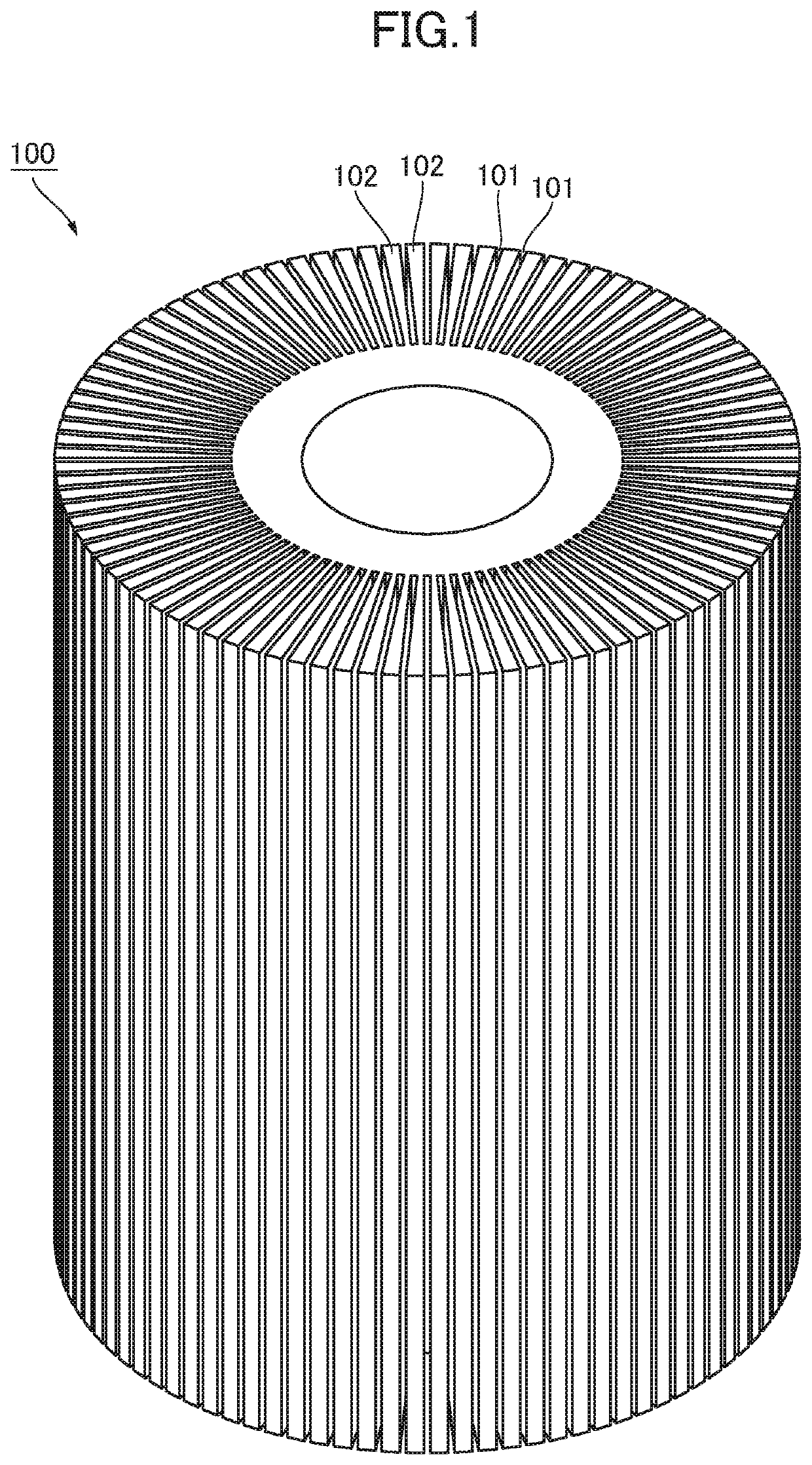
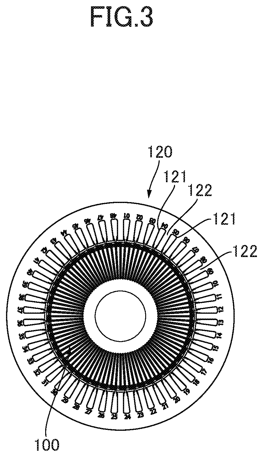
[0065]FIG. 1 shows a transfer block 100 used in the coil insertion device of the present invention. The transfer block 100 has a cylindrical shape overall, has a plurality of holding grooves 101 formed in radial fashion so as to open toward the outer periphery from an axial center part, and has a plurality of vane parts 102 that extend in radial fashion between the holding grooves 101. The transfer block 100 is configured so that a side part of coils C are inserted and held in the holding grooves 101, and so as to be inserted into the inner periphery of the stator core 120 (see FIGS. 3, 4).

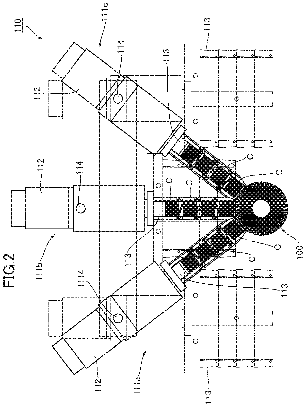
[0066]FIG. 2 shows a winding and insertion device 110 for winding the coils C and inserting the coils C into the holding grooves 101 of the transfer block 100 (corresponding to the winding machine and the device for inserting coils into the transfer block in the present invention). The winding and insertion...


PUM


Abstract

A coil insertion method includes winding U-phase, V-phase, and W-phase coils; inserting the U-phase, V-phase, and W-phase coils into a transfer block, such that the U-phase, V-phase, and W-phase coils are held in a plurality of holding grooves of the transfer block so as to spirally overlap, the transfer block having a columnar shape, and the holding grooves being formed in radial fashion around the transfer block so as to open from a center part of the transfer block toward an outer periphery thereof; inserting the transfer block into an inner periphery of the stator core; and pushing a side part of the coils held in the holding grooves radially outward toward predetermined slots of the stator core so that the coils are inserted from the inner peripheral side of the stator core into the slots.

Description

BACKGROUND OF THE INVENTION1. Field of the Invention[0001]The present invention relates to a coil insertion method and coil insertion device in which a pre-wound coil is inserted into slots of a stator core by being pushed radially outward from an inner peripheral side of the stator core.2. Description of the Related Art[0002]For example, Japanese Patent No. 4813171 discloses a method for manufacturing a stator formed by inserting one side of each of a plurality of pre-wound coils into slots and then inserting the other side of each of the plurality of coils into other slots, wherein, using a jig in which are formed on the outer periphery thereof a first holding groove group that comprises a plurality of slit-shaped holding grooves and is formed at an integer multiple pitch of the pitch of the slots of the stator core, and a second holding groove group that comprises the same number of holding grooves as the holding grooves of the first holding groove group and is formed at the same...

Claims


Application Information

Patent Timeline
Patent Type & Authority Patents(United States)
IPC IPC(8): H02K15/085H02K15/04H02K3/12H02K15/02H02K15/00
CPCH02K15/085H02K3/12H02K15/024H02K15/0464H02K15/0056H02K15/066H02K3/487
Inventor KATO, YOSHIO
Owner KATO YOSHIO
Why Eureka
Try Eureka