

Method and system for constant temperature control of motorized spindles
- Summary
- Abstract
- Description
- Claims
- Application Information
AI Technical Summary
Benefits of technology
Problems solved by technology
Method used
Image

Examples
Embodiment Construction
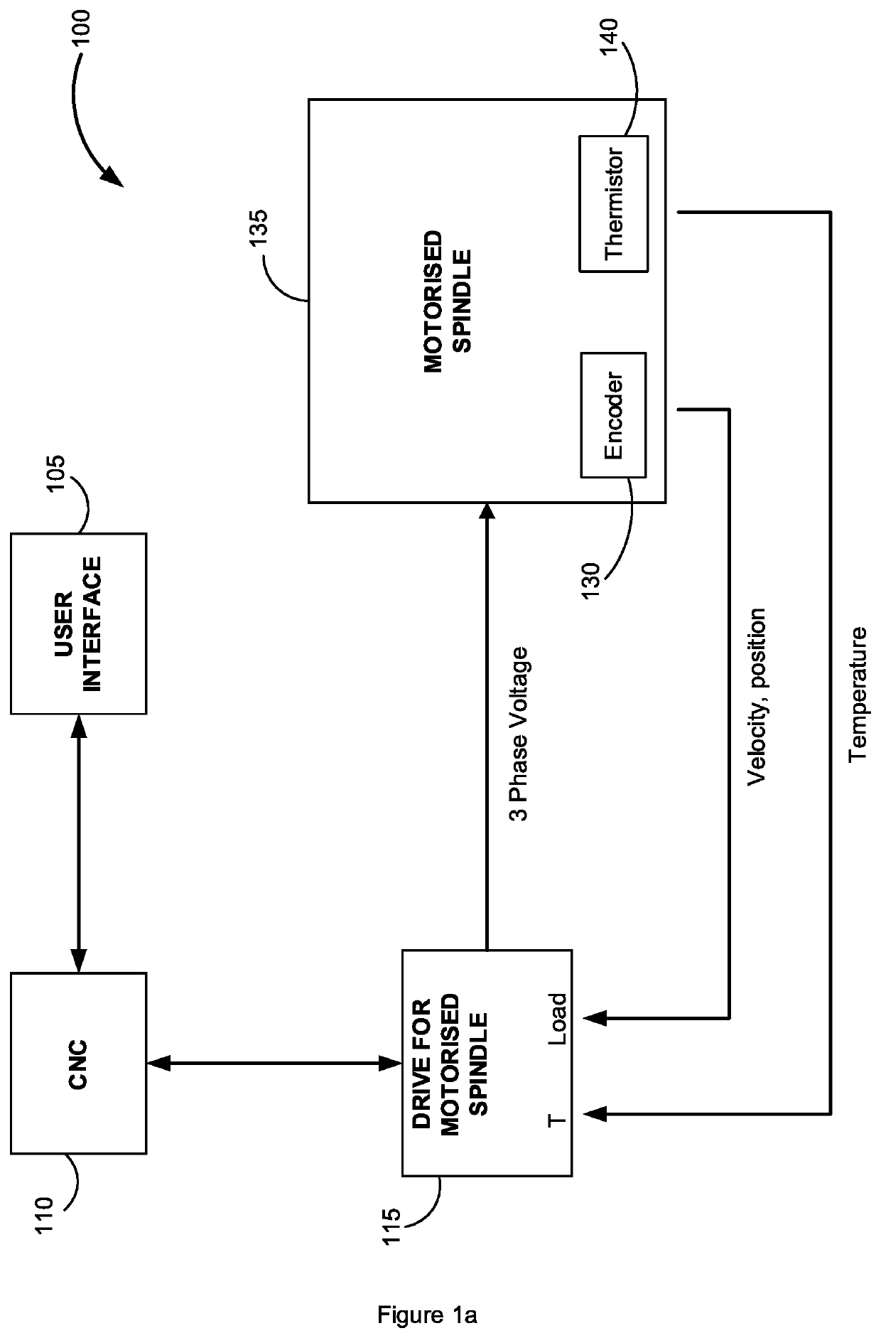
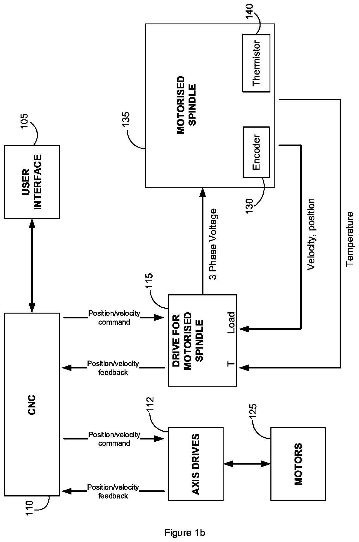
[0033]FIG. 1a is a schematic diagram of typical elements in a CNC (computer numerical controlled) system 100 used to control one or more motors and / or one or more motorised spindles. The present invention will be described with reference to motors involved in CNC environments and machine tooling but need not be limited to that. The present invention may be applied to control different types of motors in any application where constant temperature is required. In the preferred embodiment, the CNC system 100 is capable of machining complex parts to micron level tolerances.
[0034]The term ‘motorised spindle’ as used in this specification may be a motor, a spindle, or a motorised spindle. As will be appreciated, the motor 135 need not be a rotary or linear type, it could take any form including permanent magnet spindles for example. In the first embodiment, the motor 135 is an induction motor. It will be understood that in this embodiment, the magnetic flux generated by the induction moto...
PUM
 Abstract
Description
Claims
Application Information