Surgical system with medical manipulator and sterile barrier

a technology of sterile barrier and surgical system, which is applied in the field of surgical system with medical manipulator and sterile barrier, can solve the problems of surgeons who are used to perform very complex and/or physically demanding surgical procedures, surgeons can easily become fatigued, and surgeons may have to orient their hands in an awkward position

Inactive Publication Date: 2010-10-21
MICRODEXTERITY SYST
View PDF30 Cites 82 Cited by
  • Summary
  • Abstract
  • Description
  • Claims
  • Application Information

AI Technical Summary

Problems solved by technology

Conventional devices which are used to perform very complex and / or physically demanding surgical procedures like neurosurgery, spine surgery, ear surgery, head and neck surgery, hand surgery and minimally invasive surgical procedures have a number of drawbacks as it relates to the dexterity of the surgeon.
For example, the surgeon can easily become fatigued by the need to manually support the surgical device during its use.
Additionally, the surgeon may have to orient his hands in an awkward position in order to operate the device.
Furthermore, conventional devices used in such surgical procedures can produce angular magnification of errors.
However, the use of powered manipulators in medical, and in particular surgical, procedures raises other issues.
One such issue relates to sterilization.
In most cases, discarding a powered manipulator after a single use is not economically feasible.
Yet, in many cases, sterilizing a powered manipulator is also not a realistic option due to the size of the manipulator or the complexity of its electronics.
However, it can be difficult to adapt medical manipulators so that they can operate with a sterile barrier in an efficient and cost effective manner.

Method used


Image

  • Surgical system with medical manipulator and sterile barrier
  • Surgical system with medical manipulator and sterile barrier
  • Surgical system with medical manipulator and sterile barrier

Examples


Embodiment Construction

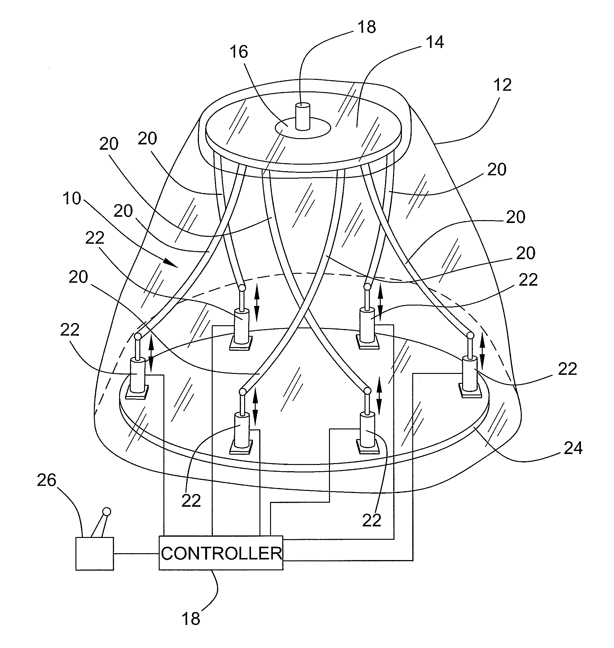
[0019]Referring now to FIG. 1 of the drawings there is shown an illustrative surgical system including a manipulator 10 that is equipped with a sterile barrier 12 in accordance with the present invention. The illustrated manipulator 10 can interchangeably support and move a medical tool with up to six degrees of freedom. While the present invention is disclosed in connection with a particular embodiment of a manipulator those skilled in the art will appreciate that is also applicable to other manipulator systems including systems which have as little as one degree of freedom. Moreover, the present invention is not limited to any particular type of medical tool. Some examples of tools that can be used include needle holders, staple or clamp appliers, probes, scissors, forceps, cautery, suction cutters, dissectors, drills, saws, lasers, ultrasonic devices and diagnostic devices.

[0020]In the illustrated embodiment, the manipulator 10 is a parallel manipulator that includes an end platf...


PUM


Abstract

A surgical system for use in performing medical procedures on a body of a patient is provided. The system can include a manipulator having a tool mounting arrangement including a modulated mechanical energy transmitter capable of transferring power. The manipulator is capable of moving the tool mounting arrangement with at least one degree of freedom. The system also includes a tool support including a modulated mechanical energy receiver capable of receiving power. A sterile barrier is arranged between the robotic mechanism and the tool support to isolate the robotic mechanism from the sterile environment. The tool support is engageable with the tool mounting arrangement with the sterile barrier therebetween and with the sterile barrier extending between the modulated mechanical energy transmitter and receiver. The modulated mechanical energy transmitter and the modulated mechanical energy receiver can transmit power across the sterile barrier between the manipulator and the tool support when the tool support is engaged with the tool mounting arrangement. The system can further include a retention mechanism configured for engaging the tool support with the tool mounting arrangement with the sterile barrier therebetween only when the tool support and tool mounting arrangement are in at least one desired orientation relative to each other.

Description

BACKGROUND OF THE INVENTION[0001]Conventional devices which are used to perform very complex and / or physically demanding surgical procedures like neurosurgery, spine surgery, ear surgery, head and neck surgery, hand surgery and minimally invasive surgical procedures have a number of drawbacks as it relates to the dexterity of the surgeon. For example, the surgeon can easily become fatigued by the need to manually support the surgical device during its use. Additionally, the surgeon may have to orient his hands in an awkward position in order to operate the device. Furthermore, conventional devices used in such surgical procedures can produce angular magnification of errors. As a result, a surgeon has considerably less dexterity and precision when performing an operation with such surgical devices than when performing an operation by traditional techniques in which the surgeon grasps a tool directly.[0002]Accordingly, there is an increasing interest in the use of powered manipulators...

Claims


Application Information

Patent Timeline
Patent Type & Authority Applications(United States)
IPC IPC(8): A61B19/00
CPCA61B19/22A61B19/26A61B2019/2226A61B2017/0023A61B2019/2296A61B2019/464A61B19/081A61B2019/2292A61B46/10A61B34/70A61B34/76A61B34/77A61B90/50A61B2034/304A61B2090/064
Inventor STUART, J. MICHAEL
Owner MICRODEXTERITY SYST
Why Eureka
Try Eureka