Lower hand guard with heat shield for use with a modular integrated rail system

a rail system and lower hand guard technology, applied in the direction of weapons, butts, weapon components, etc., can solve the problems of damage or destruction of attachments that are mounted in direct contact, insufficient space on the integrated rail provided on the upper receiver to accommodate all of the desired accessories, and limited space on the upper receiver rail

Inactive Publication Date: 2010-10-28
SWAN RICHARD E
View PDF29 Cites 47 Cited by
  • Summary
  • Abstract
  • Description
  • Claims
  • Application Information

AI Technical Summary

Benefits of technology

[0015]It is therefore an object of the present invention to provide a heat shield assembly that works in connection with the lower hand guard of an S.I.R system to prevent the transfer of heat from the barrel of the firearm to an outer surface of the hand guard. It is a further object of the present invention to provide a heat shield that is integrated into the lower hand guard and includes venting that is not in alignment with the venting of the lower hand guard thereby preventing a direct radiational transfer of heat from the firearm barrel to an outer surface of the hand guard.

Problems solved by technology

However, space on the upper receiver rail is limited, and many military personnel often have multiple sighting devices that are each tailored to perform in different combat situations.
The difficulty is that there is simply not enough space on the integrated rail provided on the upper receiver to accommodate all of the desired accessories.
This type of heat can damage or destroy attachments that are mounted in direct contact with the barrel.
Additionally, the heat generated by the gun barrel is transferred to any devices mounted directly on the barrel, such as other prior art hand guards, thereby resulting in the direct transfer of enough heat to burn a user's hands and to potentially interfere with the operation of other attachments.

Method used


Image

  • Lower hand guard with heat shield for use with a modular integrated rail system
  • Lower hand guard with heat shield for use with a modular integrated rail system
  • Lower hand guard with heat shield for use with a modular integrated rail system

Examples


Embodiment Construction

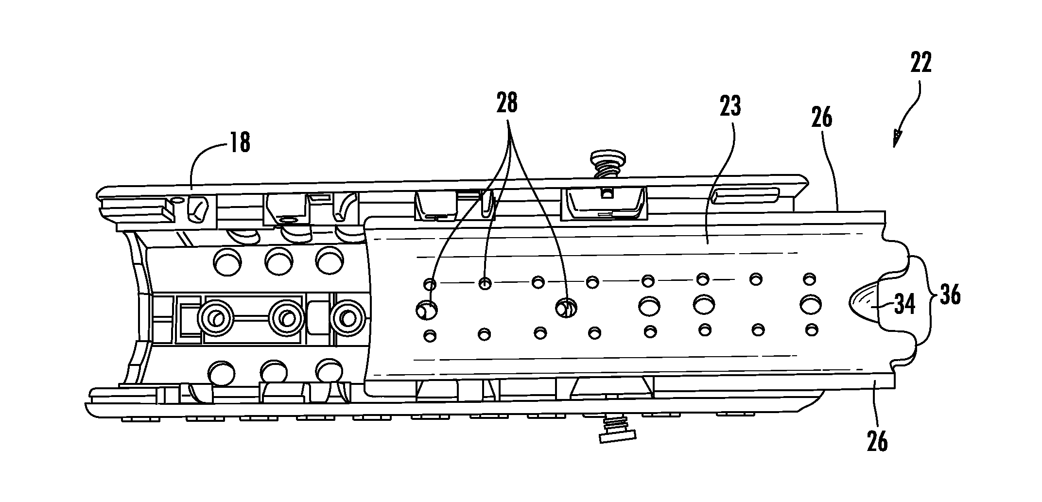
[0028]Now referring to the drawings, the heat shield of the present invention system is shown and generally illustrated at FIGS. 4-9. As can be seen, the present invention is directed to a metal heat shield insert 22 that is received into the lower hand guard 18. The heat shield 22 is received and supported in a pair of opposing mounting channels 24 that are formed on the inside of the lower hand guard 18. Generally, the heat shield 22 comprises an elongated metal sheet having a curved central body portion 23, and mounting flanges 26 extending along opposing side edges. The mounting flanges 26 are slidably received into the opposing channels 24 formed in the lower hand guard 18 to support the heat shield 22 within the interior of the lower hand guard 18. The body 23 of the heat shield 22 includes a plurality of venting holes 28 to permit air to flow through the heat shield 22. It should be noted that when the heat shield 22 is installed in assembled relation with the lower hand guar...


PUM


Abstract

A metal heat shield insert is provided for installation into the lower hand guard of an integrated rail system. The heat shield is received and supported in a pair of opposing mounting channels that are formed on the inside of the lower hand guard. The body of the heat shield includes a plurality of venting holes to permit air to flow through the heat shield. When the heat shield is installed in assembled relation with the hand guard, the venting holes in the heat shield are offset in location from the venting holes in the hand guard to provide an indirect venting arrangement.

Description

CROSS-REFERENCE TO RELATED APPLICATIONS[0001]This application is related to and claims priority from earlier filed U.S. Provisional Patent Application No. 60 / 743,249, filed Feb. 8, 2006, the contents of which are incorporated herein by reference.BACKGROUND OF THE INVENTION[0002]The present invention relates generally to modular integrated rail assemblies for combat weapons. More specifically the present invention relates to a heat shield for the lower hand guard of the rail system.[0003]As the field of combat and commercial weaponry expands, numerous add-on enhancements have become available for attachment to standard firearms, thereby significantly upgrading the capability of the firearm. Of particular interest in the area of combat weapons is the well-known M16 / M4 weapon system (M16 and M4 are trademarks of Colt Defense, Inc.). The M16 has been in service for a number of years and will continue to be a popular rifle both in U.S. and foreign militaries for the foreseeable future. G...

Claims


Application Information

Patent Timeline
Patent Type & Authority Applications(United States)
IPC IPC(8): F41A13/12F41C23/16F41C23/18
CPCF41C23/18F41C23/16
Inventor SWAN, RICHARD E.
Owner SWAN RICHARD E
Why Eureka
Try Eureka