Force feedback system including multi-tasking graphical host environment and interface device

a technology of force feedback and host environment, applied in the field of interface devices, can solve problems such as system or method of doing, use of force feedback, and many problems, and achieve the effects of preventing conflicts, great flexibility, and maximum compatibility

Inactive Publication Date: 2010-10-28
IMMERSION CORPORATION
View PDF45 Cites 16 Cited by
  • Summary
  • Abstract
  • Description
  • Claims
  • Application Information

AI Technical Summary

Benefits of technology

[0015]In another aspect of the present invention, a force feedback device, such as a force feedback mouse, provides only relative positions to a host computer. A local microprocessor on the force feedback device determines a delta position of the manipulandum that includes the change in position of the manipulandum from a previous position, and the delta position is reported to the host. A screen position of the cursor is modeled from the delta position and the modeled screen position is used in the determination of a force output by actuators of the device. An actual screen position of the cursor is received from the host computer and the modeled screen position is corrected based on the actual screen position. Preferably, the modeled screen position is corrected incrementally over time to smooth out the correction and reduce a perception of the error correction by the user. Preferably, both the host and the device adjust the screen position using a ballistics algorithm. The host also preferably sends ballistic parameters and screen size to the device to allow accurate modeling of the screen position.
[0017]Also described herein are several force feedback sensations and structures, including enclosures, textures, and grids. For example, an enclosure is a rectangular or elliptical shape having walls that provide forces to an associated graphical object such as an icon or window. The enclosure includes walls, where each wall may be associated with a force. In one embodiment, a particular type of enclosure is provided to modify the forces of a different enclosure to prevent conflicts between the forces of overlapping or closely-positioned enclosures.
[0018]The present invention provides several embodiments of components in a force feedback system. The architecture on the host computer allows multi-tasking application programs to interface with the force feedback device without conflicts. The force feedback device provides both relative position reporting and absolute position reporting to allow great flexibility. A relative position reporting device allows maximum compatibility with existing software. Information such as ballistic parameters and screen size sent from the host to the force feedback device allow accurate mouse positions and cursor positions to be determined in the force feedback environment.

Problems solved by technology

When implementing force feedback sensations in a GUI of an operating system, several problems can arise.
One problem is the use of force feedback when multiple application programs are simultaneously running in a multi-tasking environment on the host computer.
The force feedback device typically cannot store all possible force sensations for each application running in the operating system, so there is a problem of which force sensations the force feedback device should store and implement at any one time.
In addition, if two of the multi-tasking applications command conflicting force sensations, the force feedback device needs to choose one of the force sensations to output, and there currently is no system or method of doing so.
A different problem occurs when using a force feedback device with a GUI.
In addition, some types of interface devices such as trackballs are better suited to relative position reporting since an absolute, limited workspace is not easily defined for these devices.
Another problem occurs when force feedback is implemented with a GUI or other graphical environment and the graphical environment changes resolution or aspect ratio.
Using prior art force feedback devices, forces can become distorted from such an aspect ratio change.

Method used


Image

  • Force feedback system including multi-tasking graphical host environment and interface device
  • Force feedback system including multi-tasking graphical host environment and interface device
  • Force feedback system including multi-tasking graphical host environment and interface device

Examples


embodiment 290

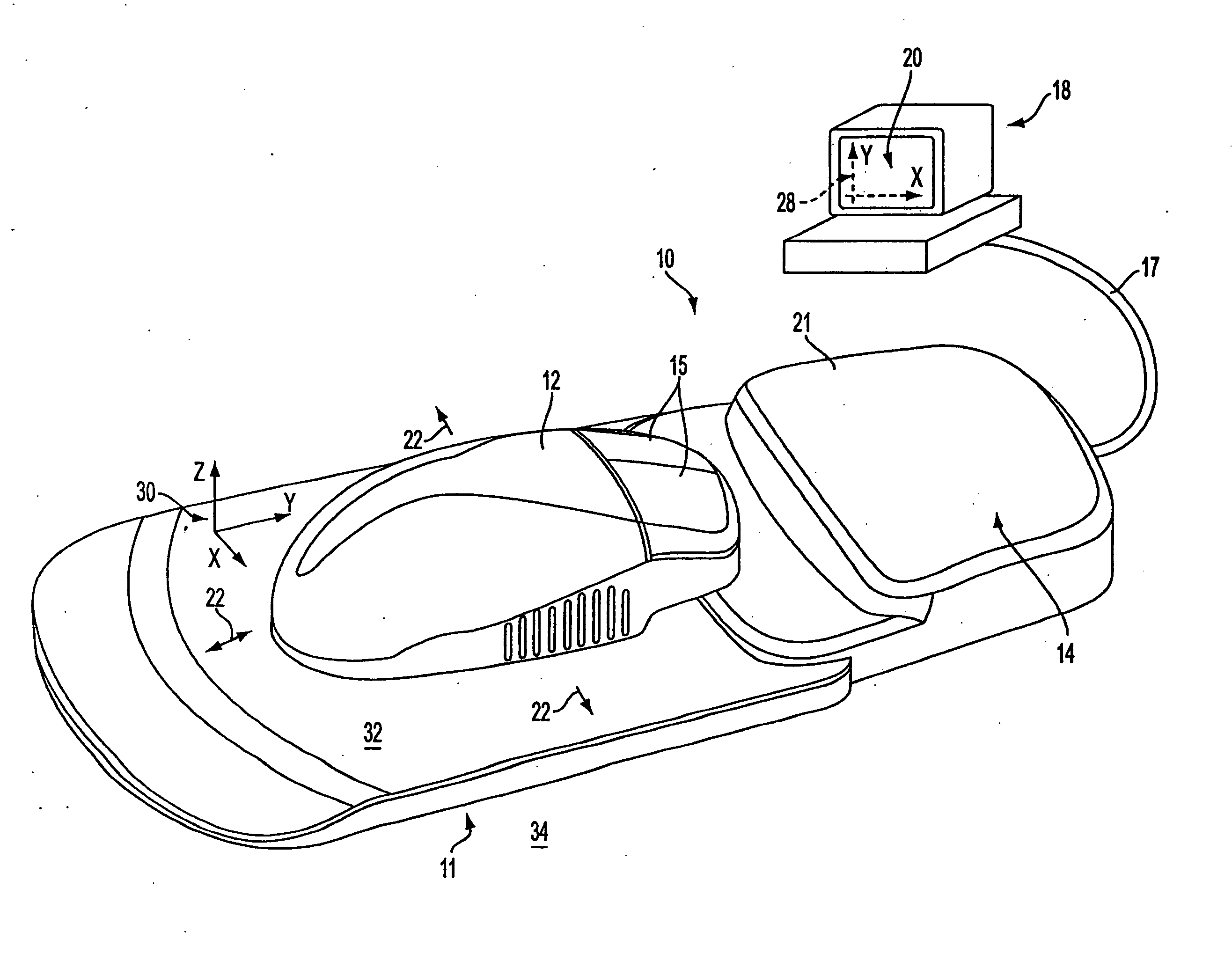
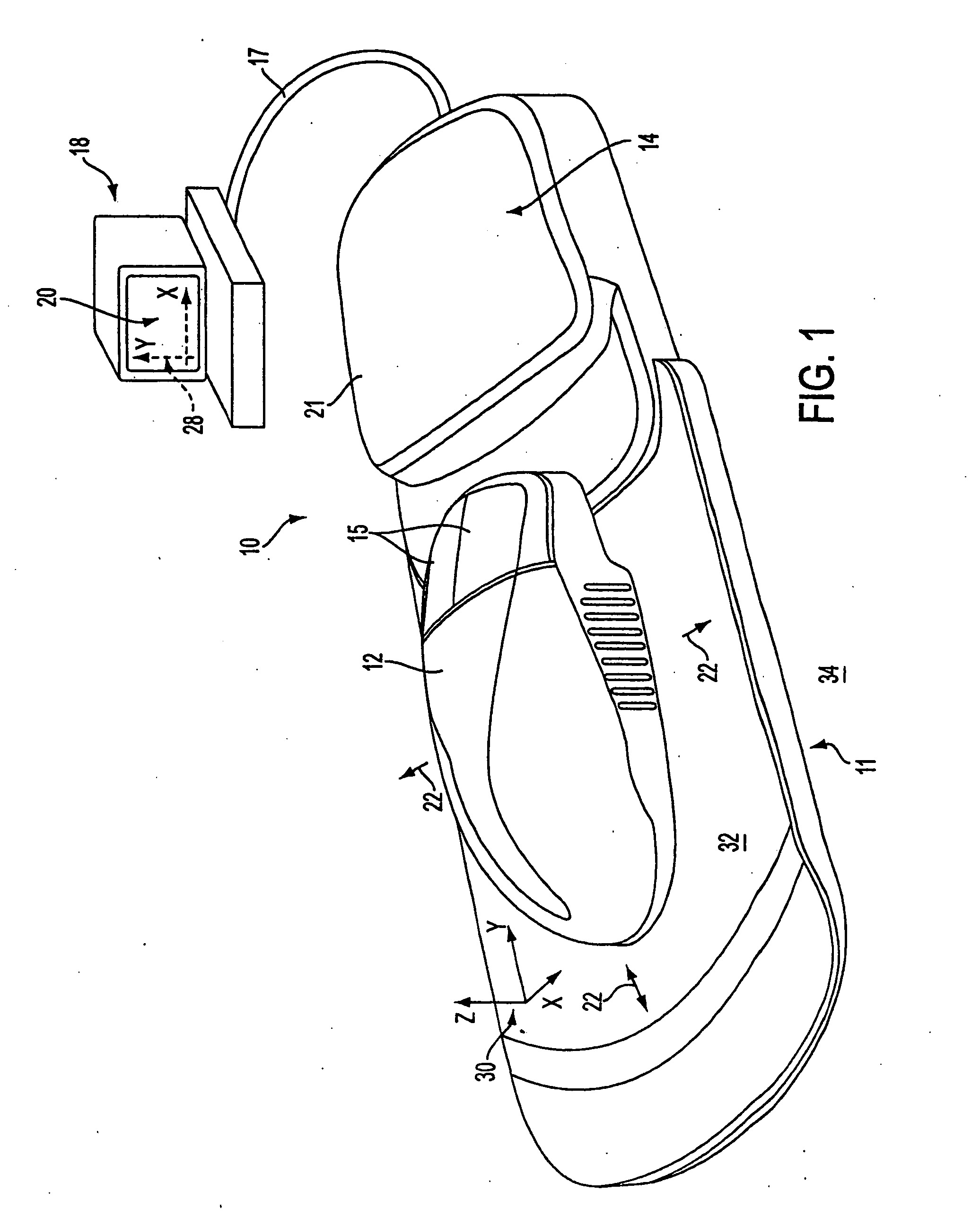
[0186]FIG. 9 is a block diagram illustrating a first, preferred embodiment 290 of the present invention. In this embodiment, both relative and absolute position reporting modes are used. As referred to herein, relative position reporting means that the force feedback device reports only changes in position of the user object 12 to the host computer, i.e. a difference between a new position and the last reported position, while absolute position reporting means that absolute coordinates are reported to the host from which the host can directly display the cursor or other graphical object. Most force feedback controllers use absolute position reporting since the position of the cursor on the screen must be known to implement forces. For example, the force feedback mouse and other interface devices described in U.S. Pat. Nos. 6,219,032, 5,825,308, and 6,100,874 use absolute position reporting.

[0187]One problem with absolute position reporting is that the host computer cannot detect the...

embodiment 400

[0218]Embodiment 400 provides a device delta position to the host computer from which the host computer determines a cursor screen pixel position. The host computer sends cursor position updates to the force feedback device to provide the cursor position which the device needs to determine when forces are output and to determine the force characteristics. However, since the host cursor position updates occur at a much slower rate, the device must model the cursor position on its own to be able to output forces between host cursor updates. Thus, the host sends ballistic parameters and screen size information so the device can model the cursor position. When the device receives an update, it corrects for any error between its modelled position and the actual cursor position, as detailed below. The host also sends force feedback commands to the device indicate which forces are to be output.

[0219]FIG. 13 illustrates a process 410 for implementing the second embodiment 400 of FIG. 12. A ...


PUM


Abstract

A force feedback system provides components for use in a force feedback system including a host computer and a force feedback interface device. An architecture for a host computer allows multi-tasking application programs to interface with the force feedback device without conflicts. One embodiment of a force feedback device provides both relative position reporting and absolute position reporting to allow great flexibility. A different device embodiment provides relative position reporting device allowing maximum compatibility with existing software. Information such as ballistic parameters and screen size sent from the host to the force feedback device allow accurate mouse positions and cursor positions to be determined in the force feedback environment. Force feedback effects and structures are further described, such as events and enclosures.

Description

CROSS REFERENCE TO RELATED APPLICATIONS[0001]This application is a continuation of pending U.S. application Ser. No. 09 / 974,197 filed on Oct. 9, 2001, which is also a continuation of U.S. application Ser. No. 08 / 970,953, filed Nov. 14, 1997, now U.S. Pat. No. 6,300,936, issued on Oct. 9, 2001, and entitled “Force Feedback System Including Multi-Tasking Graphical Host Environment and Interface Device”, in the names of the same inventors and commonly owned herewith.[0002]This invention was made with Government support under Contract Number F41624-96-C-6029, awarded by the Department of Defense. The Government has certain rights in this invention.BACKGROUND OF THE INVENTION[0003]The present invention relates generally to interface devices for allowing humans to interface with computer systems, and more particularly to computer interface devices that allow the user to provide input to computer systems and provide force feedback to the user.[0004]Computer systems are used extensively to ...

Claims


Application Information

Patent Timeline
Patent Type & Authority Applications(United States)
IPC IPC(8): G08B6/00G09G5/00G05B19/00G06F3/00G06F3/01G06F3/033H04L29/08
CPCG05B19/00G06F3/016G06F3/03543G06F3/03548H04L69/329G06F2203/014G06F2203/0333H04L67/36H04L67/02G06F2203/013H04L67/75G06F3/0338G06F3/04842
Inventor BRAUN, ADAM C.BEAMER, JONATHAN L.ROSENBERG, LOUIS B.CHANG, DEAN C.
Owner IMMERSION CORPORATION
Why Eureka
Try Eureka