Image forming apparatus and image forming method

a technology of image forming apparatus and forming method, which is applied in the direction of electrographic process apparatus, instruments, optics, etc., can solve the problems of difficult to perform the transferring satisfactorily, difficult to reliably separate the transfer material, and none of the proposed solutions have drawbacks, so as to achieve convenient separation of the transfer material, separate, and separate

Inactive Publication Date: 2010-10-28
SEIKO EPSON CORP
View PDF10 Cites 11 Cited by
  • Summary
  • Abstract
  • Description
  • Claims
  • Application Information

AI Technical Summary

Benefits of technology

[0011]The transfer roller bringing the image carrying belt into pressing contact with a first roller is electrically grounded. In this way, it is possible to prevent the transfer material from being electrostatically adsorbed to the transfer roller. Accordingly, it is possible to easily separate the transfer material from the transfer roller. By doing so, it is possible to separate the transfer material subjected to...

Problems solved by technology

Unfortunately, none of these proposed solutions have drawbacks.
For example, since the image forming apparatus disclosed in Japanese Patent No. 3128067 uses only blown air to separate the front end of the transfer material, it is difficult to separate the transfe...

Method used


Image

  • Image forming apparatus and image forming method
  • Image forming apparatus and image forming method
  • Image forming apparatus and image forming method

Examples


Embodiment Construction

[0020]Hereinafter, an embodiment of the invention will be described with reference to the drawings.

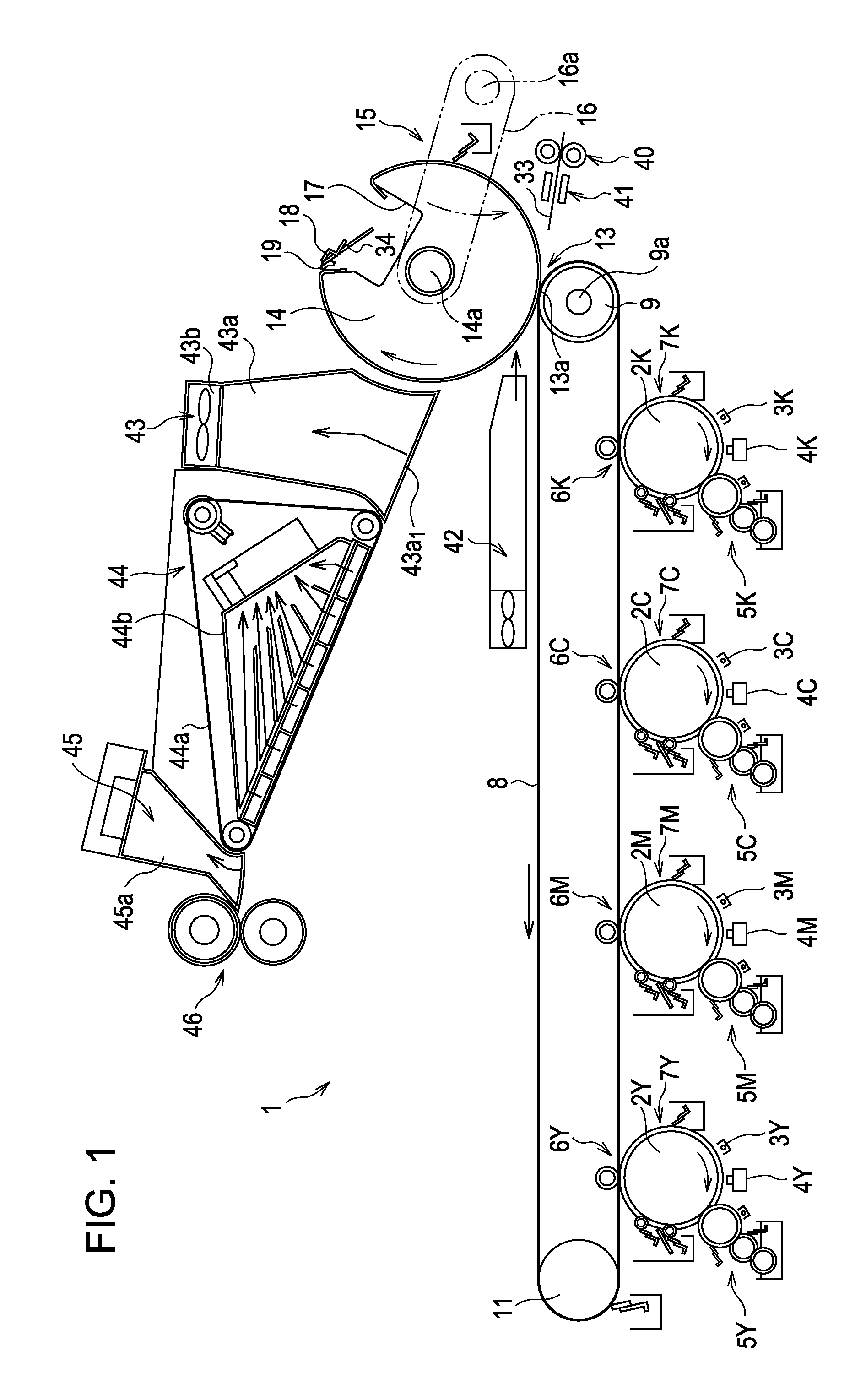
[0021]FIG. 1 is a diagram schematically illustrating a part of an image forming apparatus including a transfer device according to one embodiment of the invention.

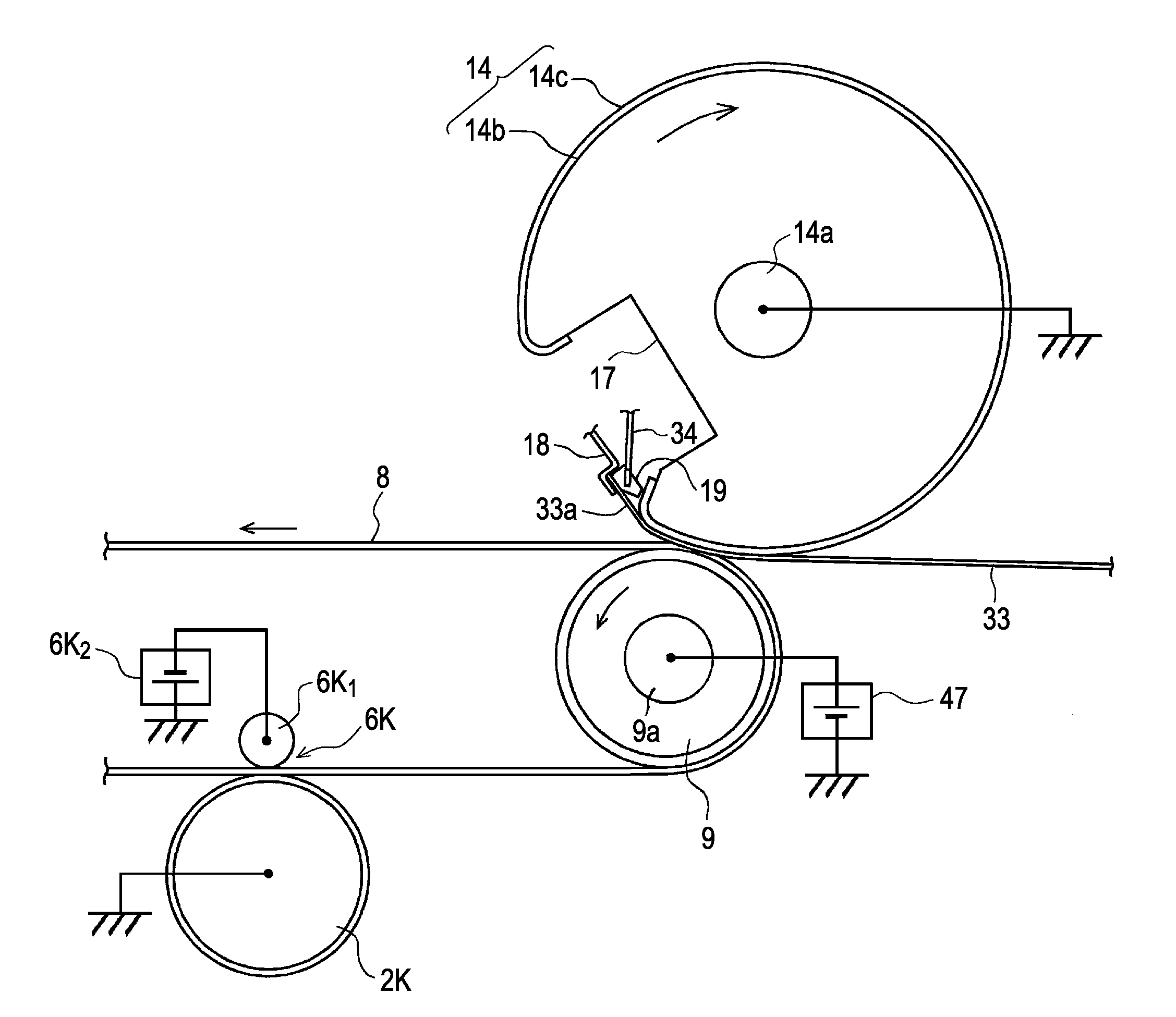
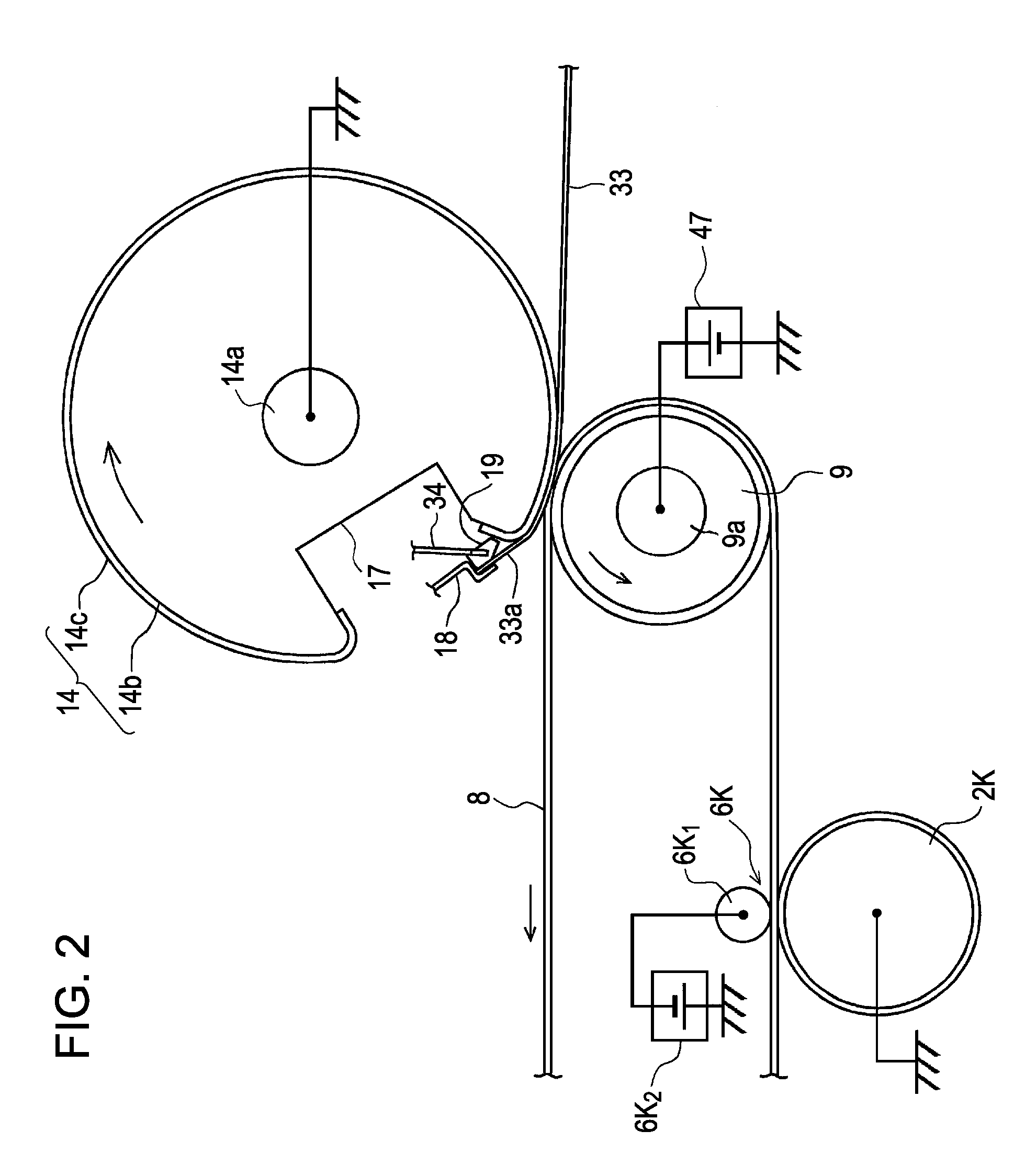
[0022]An image forming apparatus 1 according to the first embodiment forms an image using a liquid developer containing solid content toner and carrier liquid. As shown in FIG. 1, the image forming apparatus 1 includes photoconductive members 2Y, 2M, 2C, and 2K, which are image carrying members of yellow (Y), magenta (M), cyan (C), and black (K) disposed in a tandem in the horizontal or in the substantially horizontal direction. Here, the photoconductive members 2Y, 2M, 2C, and 2K, include the yellow photoconductive member 2Y, the magenta photoconductive member 2M, the cyan photoconductive member 2C, and the black photoconductive member 2K. Likewise, in other members, respective color members are denoted by adding respective ...


PUM


Abstract

An image forming apparatus including an image carrying belt which has volume resistance from 107 Ωcm to 1012 Ωcm and carries an image, a roller around which the image carrying belt is wound and which drives the image carrying belt, a transfer roller which includes a transfer material gripper which grips a transfer material which is disposed in a concaved portion of the transfer roller and which comes into pressing contact with the roller with the image carrying belt interposed therebetween so as to transfer the image carried by the image carrying belt to the transfer material, a bias applying unit which applies a transfer bias to the roller, and a ground unit which electrically grounds the transfer roller.

Description

[0001]The entire disclosure of Japanese Patent Application No. 2009-107332, filed Apr. 27, 2009 is expressly incorporated herein by reference.BACKGROUND OF THE INVENTION[0002]1. Technical Field[0003]The present invention relates to an image forming apparatus and an image forming method of an electrographic type capable of transferring an image of an image carrying member to a transfer material, such as paper, using a transfer roller including a transfer material gripper which comes into pressing contact with an image carrying belt.[0004]2. Related Art[0005]In many wet-type image forming apparatuses which use a liquid developer, since the transfer surface including the toner image comes into pressing contact with an intermediate transfer medium, the transfer material may easily become attached to the intermediate transfer medium, rather than being transferred through the apparatus as desired. In order to solve this problem, there has been suggested an image forming apparatus which se...

Claims


Application Information

Patent Timeline
IPC IPC(8): G03G15/01G03G15/16
CPCG03G15/1675G03G15/1605G03G15/162
Inventor KAMIJO, KOICHIIKUMA, KEN
Owner SEIKO EPSON CORP
Why Eureka
Try Eureka