Melt Channel Geometries for an Injection Molding System

a technology of injection molding system and melt channel, which is applied in the field of injection molding system, can solve the problems of uneven melting stream from cavity to cavity, imbalance of shear-heated material between runners and subsequently between cavities of injection molding apparatus,

Active Publication Date: 2010-10-28
MOLD MASTERS 2007
View PDF30 Cites 12 Cited by
  • Summary
  • Abstract
  • Description
  • Claims
  • Application Information

AI Technical Summary

Problems solved by technology

However, at times, despite having matched runner layouts, the melt stream may be different from cavity to cavity due to shear heating of the melt stream as it is forced along the melt path through the runners.
This phenome

Method used


Image

  • Melt Channel Geometries for an Injection Molding System
  • Melt Channel Geometries for an Injection Molding System
  • Melt Channel Geometries for an Injection Molding System

Examples


Embodiment Construction

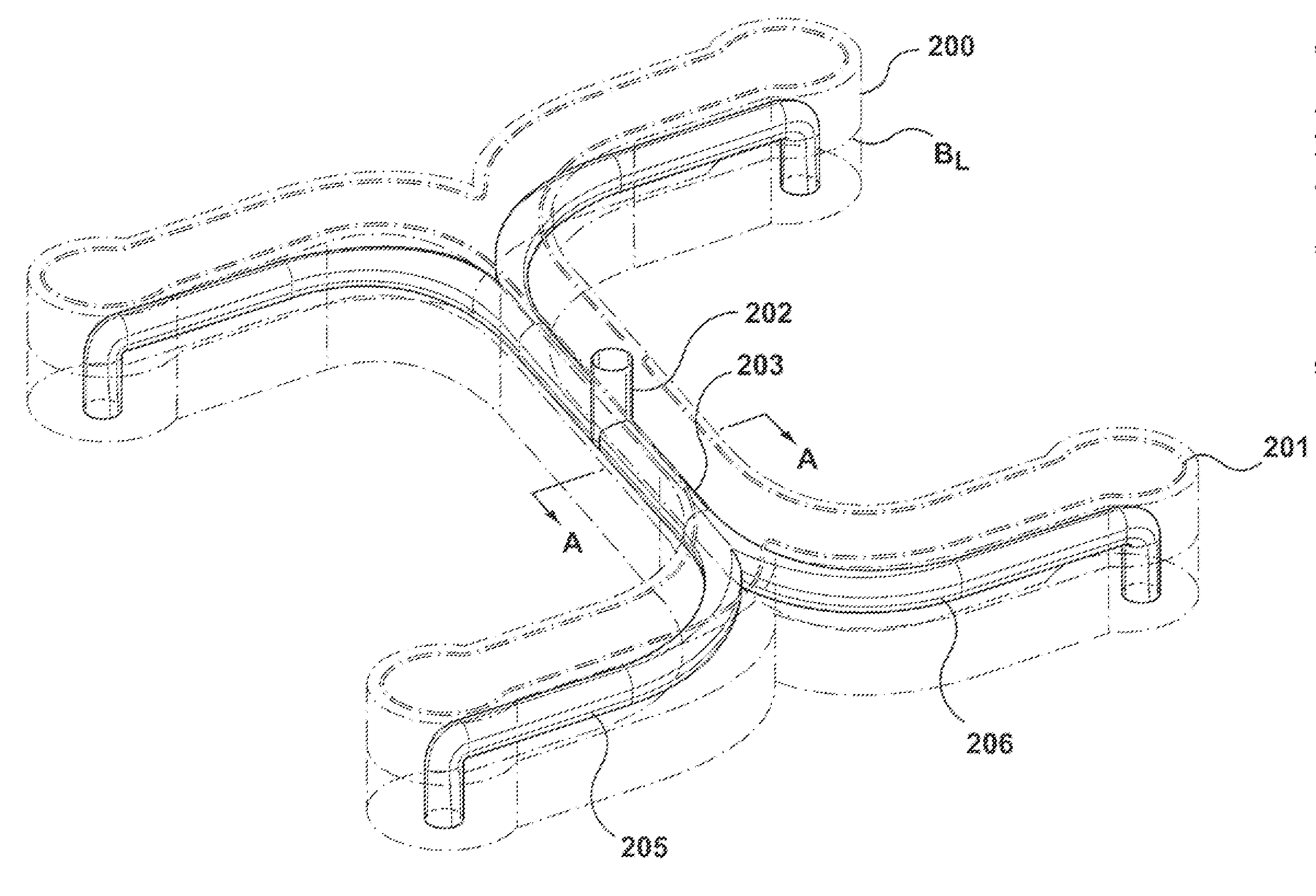
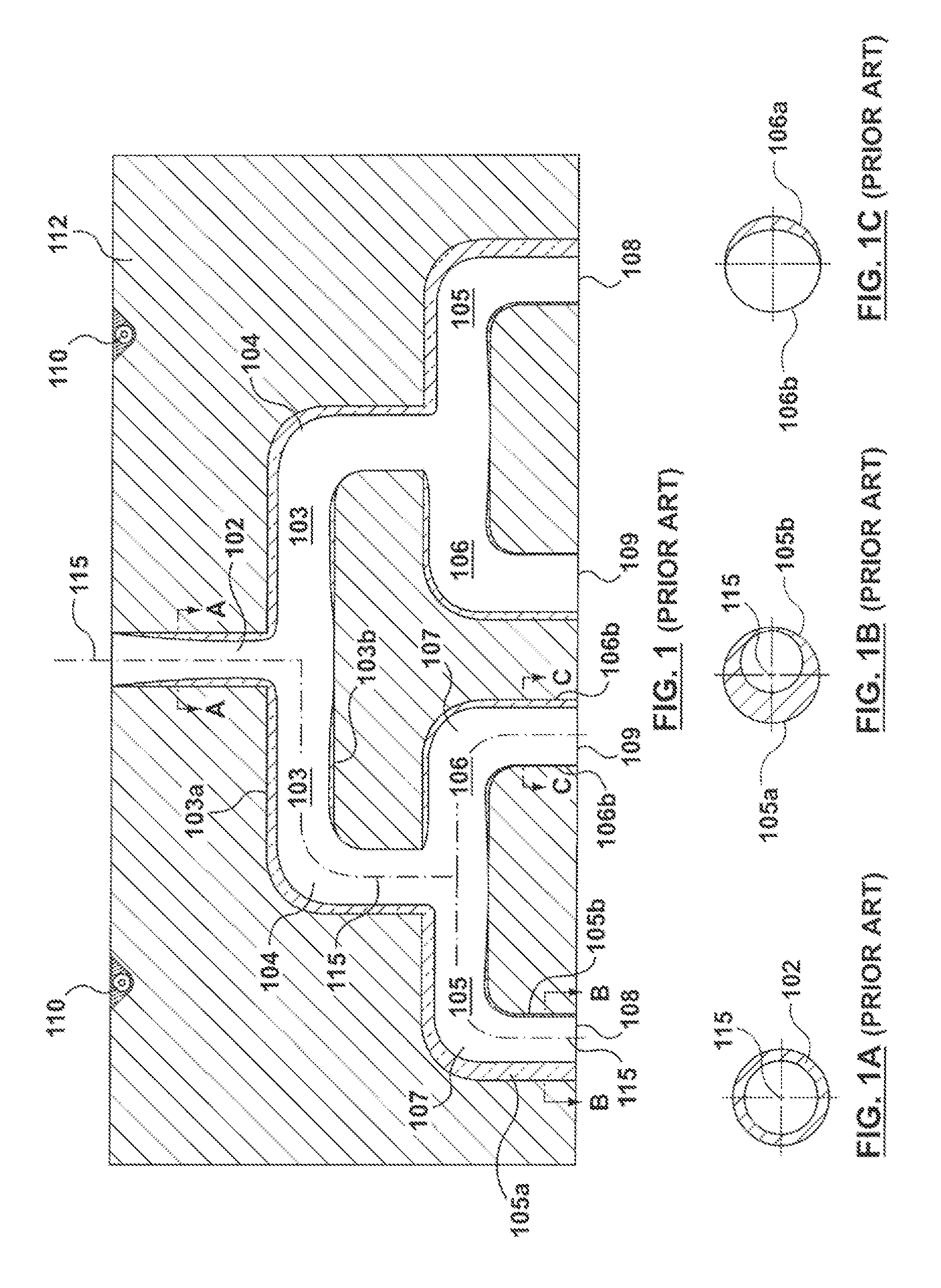
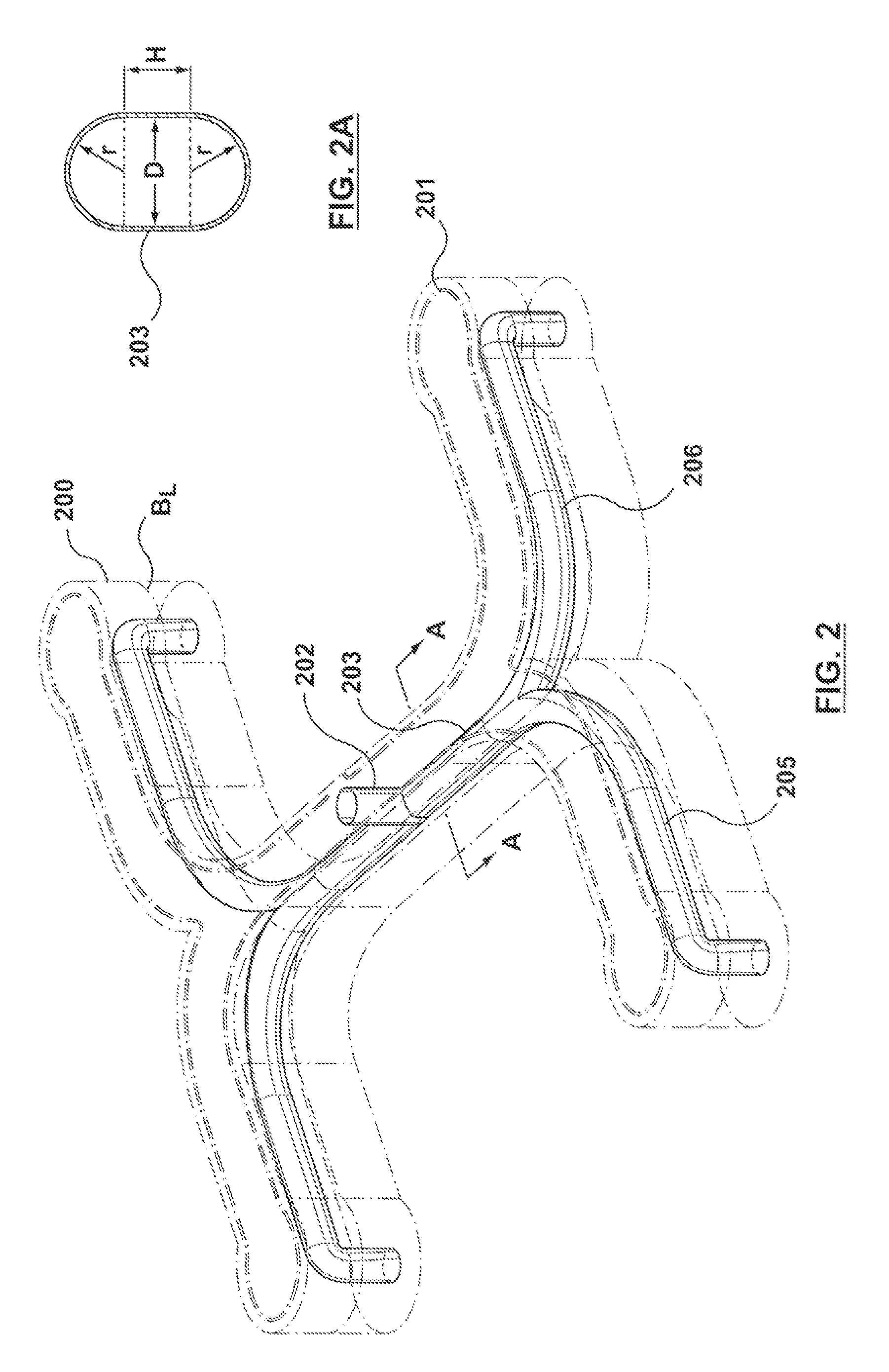
[0016]Specific embodiments of the present invention are now described with reference to the figures. The following detailed description is exemplary in nature and is not intended to limit the invention or the application and uses of the invention. In the following description, “downstream” is used with reference to the direction of mold material flow from an injection unit to a mold cavity of an injection molding system and also to the order of components or features thereof through which the mold material flows from an inlet of the injection molding system to a mold cavity, whereas “upstream” is used with reference to the opposite direction. Although the description of the invention is in the context of a manifold in a hot runner injection molding system, the invention may also be used in any melt channel along the melt path from the melt source to the mold cavity where it is deemed useful. Furthermore, there is no intention to be bound by any expressed or implied theory presented ...


PUM

PropertyMeasurementUnit
Perimeteraaaaaaaaaa
Perimeteraaaaaaaaaa
Perimeteraaaaaaaaaa

Abstract

An injection molding system is disclosed that utilizes a melt channel wherein at least a portion of the melt channel has a noncircular cross-section for balancing shear in a melt stream of moldable material that flows therethrough. The noncircular cross-section of the melt channel portion may be, for e.g., capsule-shaped, extended egg-shaped, oval, teardrop-shaped, or peanut-shaped. A flow splitter is also disclosed that is positioned offset from a central axis of an upstream melt channel to protrude between inlets of respective downstream melt channels, where the upstream melt channel splits into the downstream melt channels, to thereby create a narrower inlet into one of the downstream melt channels and a wider inlet into the other of the downstream melt channels.

Description

CROSS-REFERENCE TO RELATED APPLICATION[0001]This application claims the benefit under 35 U.S.C. §119(e) of U.S. Appl. No. 61 / 172,824 filed Apr. 27, 2009, the disclosure of which is incorporated by reference herein in its entirety.FIELD OF THE INVENTION[0002]The invention relates generally to an injection molding system, and more specifically to the melt channel geometries for balancing or improving properties of a melt stream of moldable material flowing through the components along the melt path of the injection molding system.BACKGROUND OF THE INVENTION[0003]The use of manifolds in injection molding systems to transfer a melt stream from a melt source to one or more nozzles for delivering melt to one or more mold cavities is well known in the art. Furthermore, it is well known that in many hot runner injection molding applications it is important that a manifold melt channel layout, which is also known in the art as a runner system, be provided such that each mold cavity receives ...

Claims


Application Information

Patent Timeline
IPC IPC(8): B29C45/73
CPCB29C45/03B29C45/2704B33Y80/00B29C45/74B29L2031/757
Inventor KAUSHAL, HITESHGODWIN, HAROLD
Owner MOLD MASTERS 2007
Why Eureka
Try Eureka