Exit lane monitoring system

a technology of exit lane and monitoring system, applied in the field of security, can solve the problems of no one having proved flawless, time-consuming and expensive, and a great deal of aggravation and hard feelings on the part of the user, and achieve the effect of reducing the number of exit lane monitoring devices

Inactive Publication Date: 2014-06-10
TEN4WARD
View PDF26 Cites 8 Cited by
  • Summary
  • Abstract
  • Description
  • Claims
  • Application Information

AI Technical Summary

Benefits of technology

[0010]The present disclosure is directed to an exit lane monitor system (ELMS) which effectively secures an exit from a breach on the public side of the passage while allowing the free egress of people from the secure side.

Problems solved by technology

Some of these systems have been found to be more effective than others, but none have proved flawless.
This is not only time consuming and expensive, but results in a great deal of aggravation and hard feelings on the part of those simply trying to catch an airplane.
In addition, placing one or more guards in the exit lane is costly.
The result is in having to hire, train, and pay a number of people just to guard the exit.
To date, none of the studies have demonstrated a truly satisfactory solution to the problem of exit lane breach control (ELBC).
Gates have been found to have too many safety issues associated with them to be operable in a way that they can be rapidly closed without potentially harming people in the exit passage.
Turnstiles do not provide sufficient throughput, as well as having too large a footprint to comply with fire / safety codes for the exit lane volume they are required to handle.
Another drawback is the amount of processing and data storage capability required for the system and which imposes a substantial cost on system implementation.
Further, while these detection systems do detect intruders or wrong-way travelers, effectively implementing them is difficult to do, as there are many different intrusion scenarios which can cause the system to fail.
Another problem with them is that even though they are capable of detecting the violation, they need to be integrated with a deterrent or capture system that can operate rapidly enough to prevent the intruder from entering the access controlled space.

Method used


Image

  • Exit lane monitoring system
  • Exit lane monitoring system
  • Exit lane monitoring system

Examples


Embodiment Construction

[0025]The following detailed description illustrates the invention by way of example and not by way of limitation. This description clearly enables one skilled in the art to make and use the invention, and describes several embodiments, adaptations, variations, alternatives and uses of the invention, including what is presently believed to be the best mode of carrying out the invention. Additionally, it is to be understood that the invention is not limited in its application to the details of construction and the arrangement of components set forth in the following description or illustrated in the drawings. The invention is capable of other embodiments and of being practiced or carried out in various ways. Also, it will be understood that the phraseology and terminology used herein is for the purpose of description and should not be regarded as limiting.

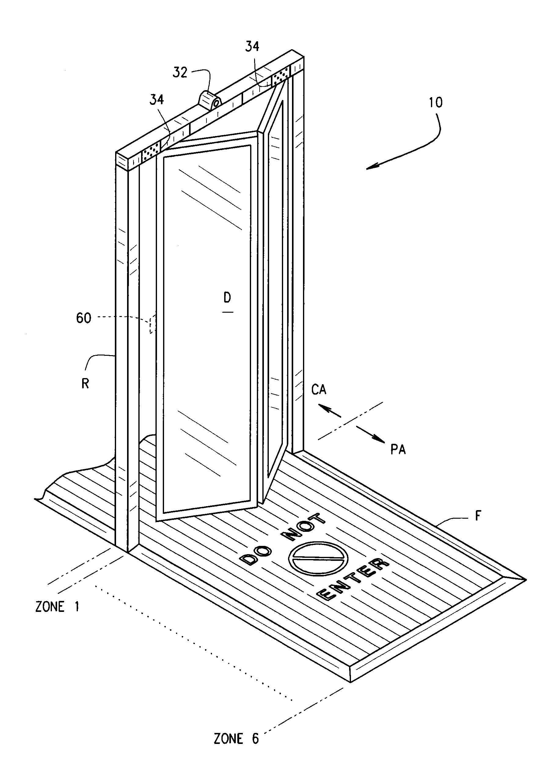
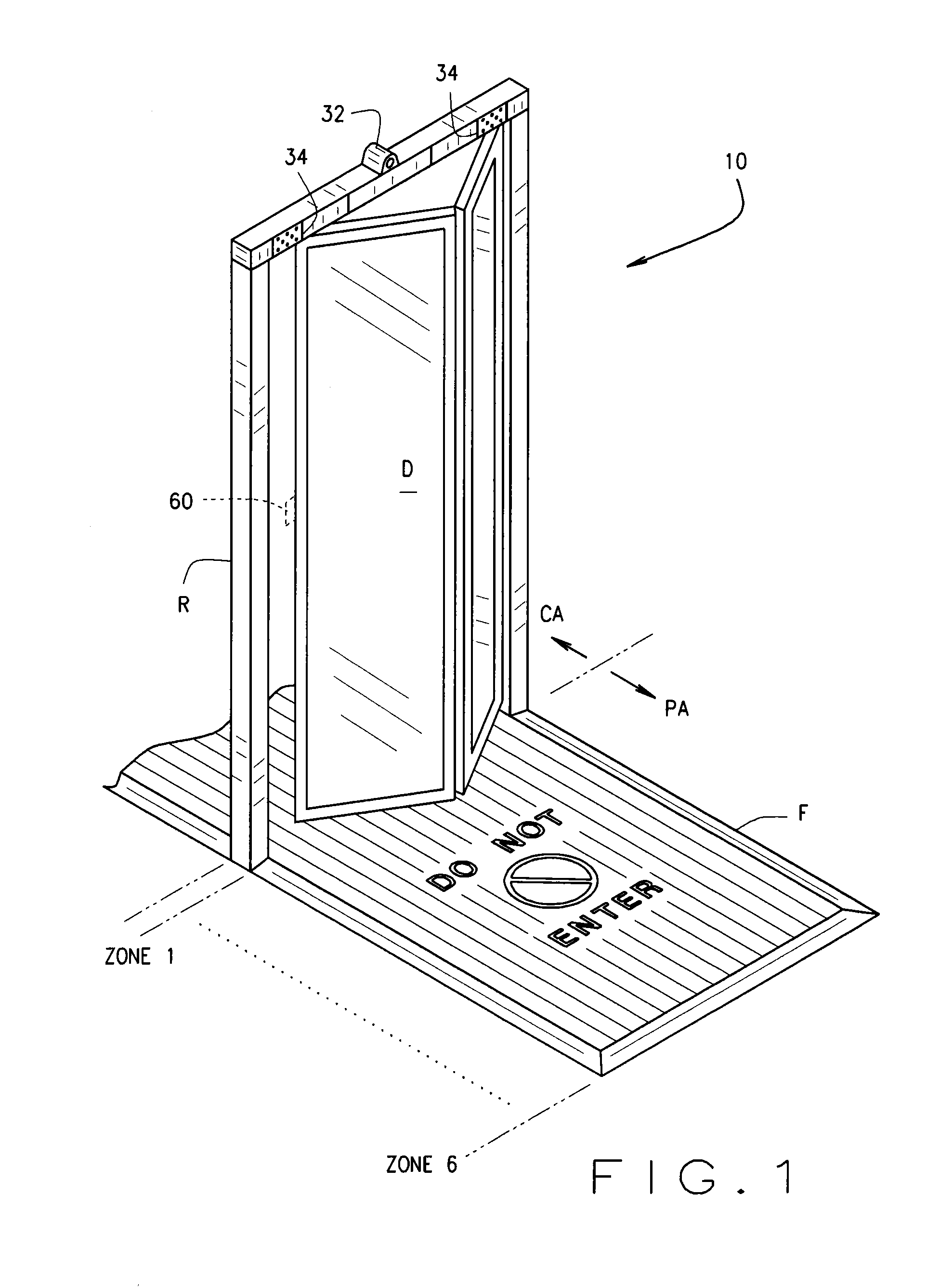
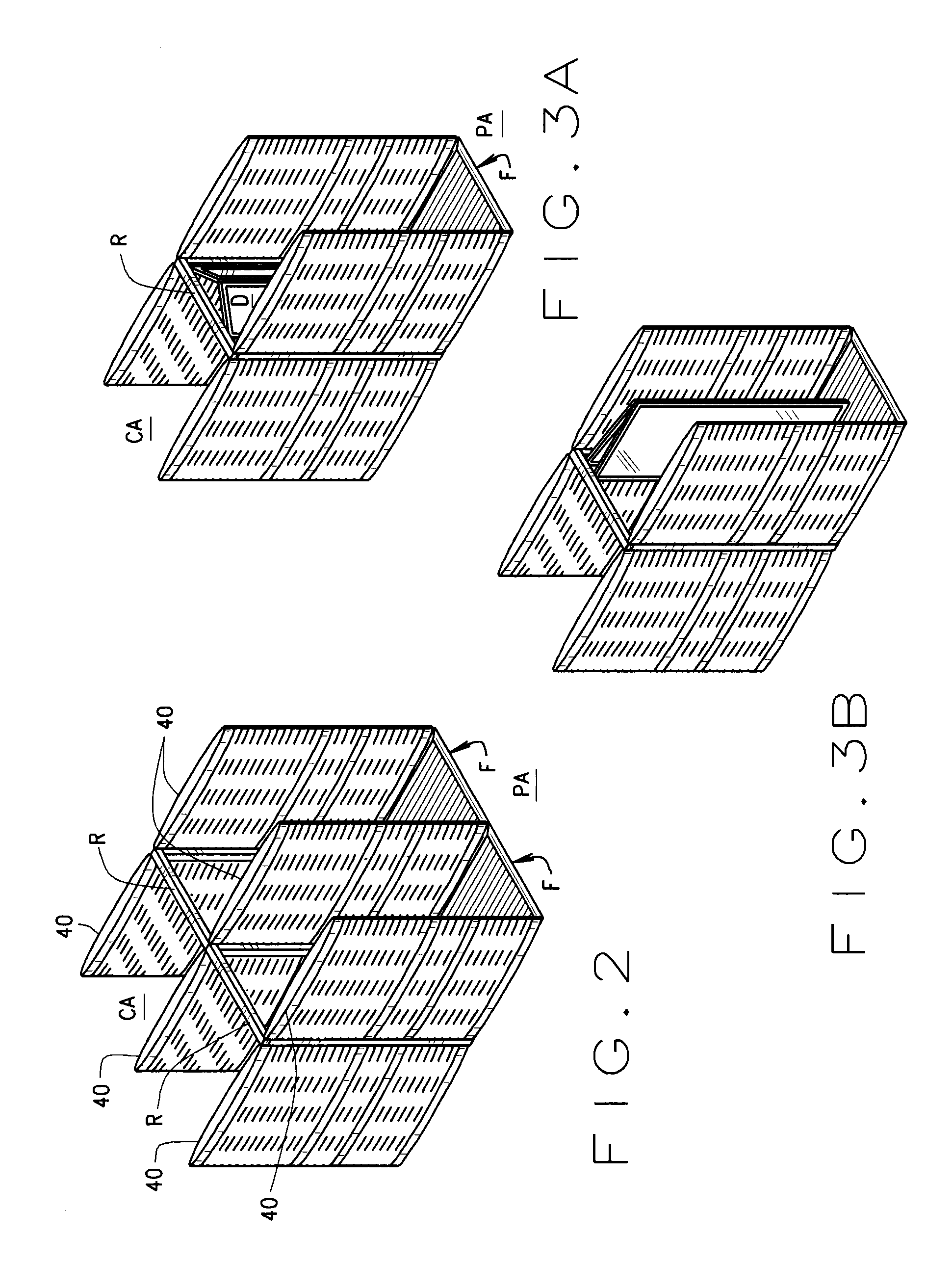
[0026]Referring to the drawings, an exit lane monitoring system (ELMS) for detecting and blocking wrong-way movement through a pas...


PUM

PropertyMeasurementUnit
lengthaaaaaaaaaa
areaaaaaaaaaaa
foot pressureaaaaaaaaaa

Abstract

An exit lane monitoring system (10) detects wrong-way movement through a passage (P) between a secure area and a public area. Heel before toe sensors (12) are positioned on the floor of the passage and detect the foot pressure exerted by people moving through the passage from the secure area toward the public area and of persons moving the wrong way through the passage. Positioning of the sensors in the passage depends upon the geometry of the passage so sensors may be oriented in a non-geometric pattern if so dictated by the passage's geometry. A door (D) is selectively operated to block the passage and prevent persons moving the wrong way through it from entering the secure area. A control unit (16) is responsive to a sensor indication that someone is moving the wrong way to activate the door to block the passage and prevent movement into the secure area.

Description

CROSS REFERENCE TO RELATED APPLICATIONS[0001]U.S. provisional patent application 61 / 430,239 filed Jan. 6, 2011.STATEMENT REGARDING FEDERALLY SPONSORED RESEARCH OR DEVELOPMENT[0002]NoneBACKGROUND OF THE INVENTION[0003]This invention relates to security in access controlled areas in venues such as airports and government offices; and, more particularly, to a detection system in combination with a deterrent system which completely restricts travel in one (the wrong) direction while allowing free access in the opposite (secure side to public side) direction.[0004]In many venues, particularly airports and the like, it is not only desirable, but mandatory that access into secure areas (e.g., an airport concourse) be rigidly controlled so that only people who have passed through some type of screening procedure are allowed into the secure area. Using the airport example, people who have passed the screening procedure are allowed to enter the secure area through one passage (entry lane); wh...

Claims


Application Information

Patent Timeline
Patent Type & Authority Patents(United States)
IPC IPC(8): G05B19/00E05B45/06A47L17/08G08B23/00
CPCG08B13/08G07C9/00G07C9/15
Inventor BRUNETTI, SAM, F
Owner TEN4WARD
Why Eureka
Try Eureka