Filter element and soot filter having geometrically similar channels

Inactive Publication Date: 2010-02-18
ROBERT BOSCH GMBH
View PDF22 Cites 8 Cited by
  • Summary
  • Abstract
  • Description
  • Claims
  • Application Information

AI Technical Summary

Benefits of technology

[0007]An object of the present invention is to provide a filter element for a soot filter and a soot filter in which the temperature distribution over the cross-section of the filter

Problems solved by technology

This strongly reduces the heat transfer of part of the filter element to the environ

Method used


Image

  • Filter element and soot filter having geometrically similar channels
  • Filter element and soot filter having geometrically similar channels
  • Filter element and soot filter having geometrically similar channels

Examples


Embodiment Construction

[0024]FIG. 1 shows a soot filter 1 having a feed line 3, a diffusor 5, a housing 7, and a filter element according to the present invention 9 in a partially sectioned side view.

[0025]The flow passes through soot filter 1 in the direction of arrows 11. Housing 7 is connected to a cone 13 and an outlet line 15. Filter element 9 is gas-tightly connected to the housing, so that the exhaust gas (not depicted) entering through feed line 3 must flow through filter element 9.

[0026]Filter element 9 has an inlet face 17 and an outlet face 19. A plurality of channels extending from inlet face 17 to outlet face 19 pass through filter element 19.

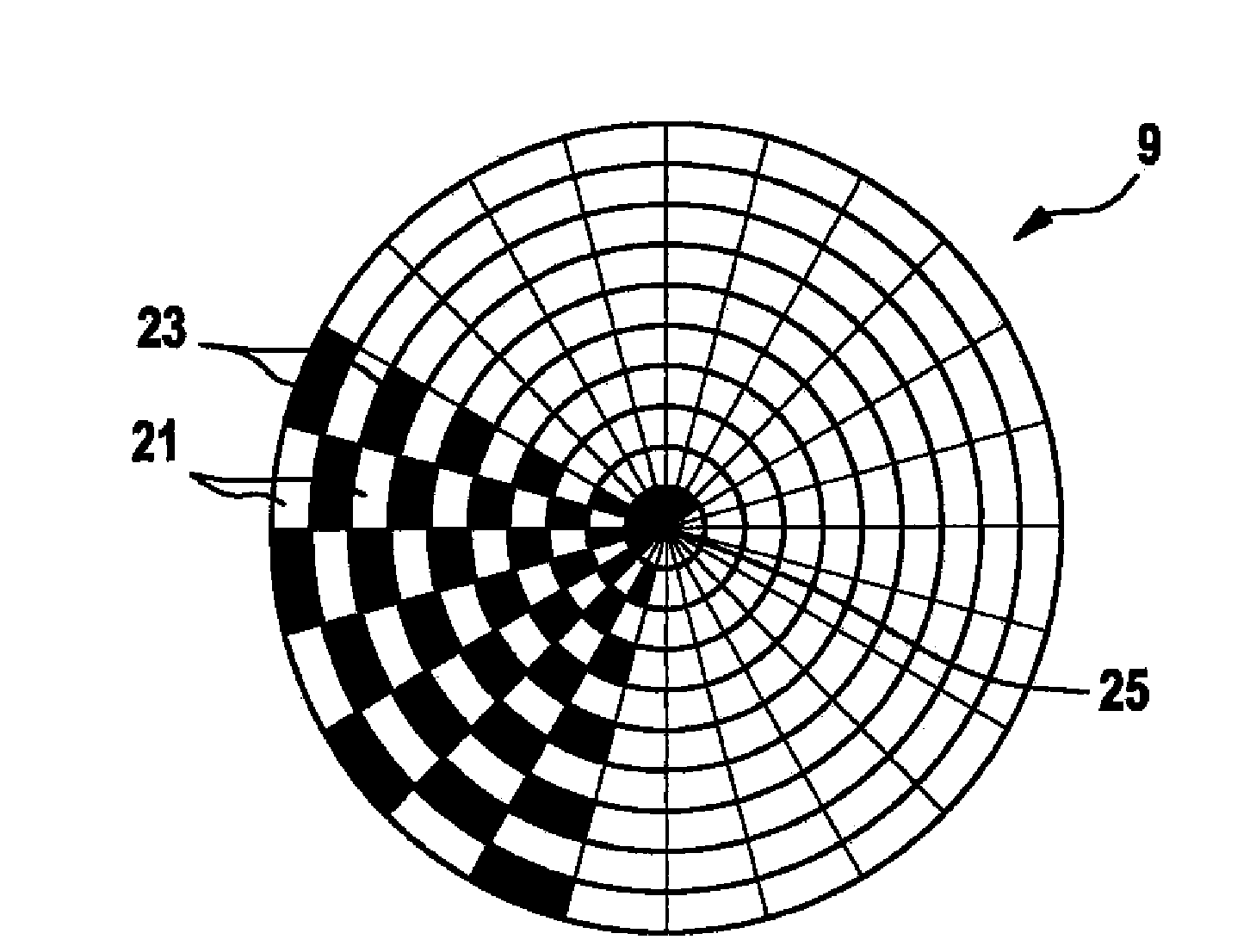
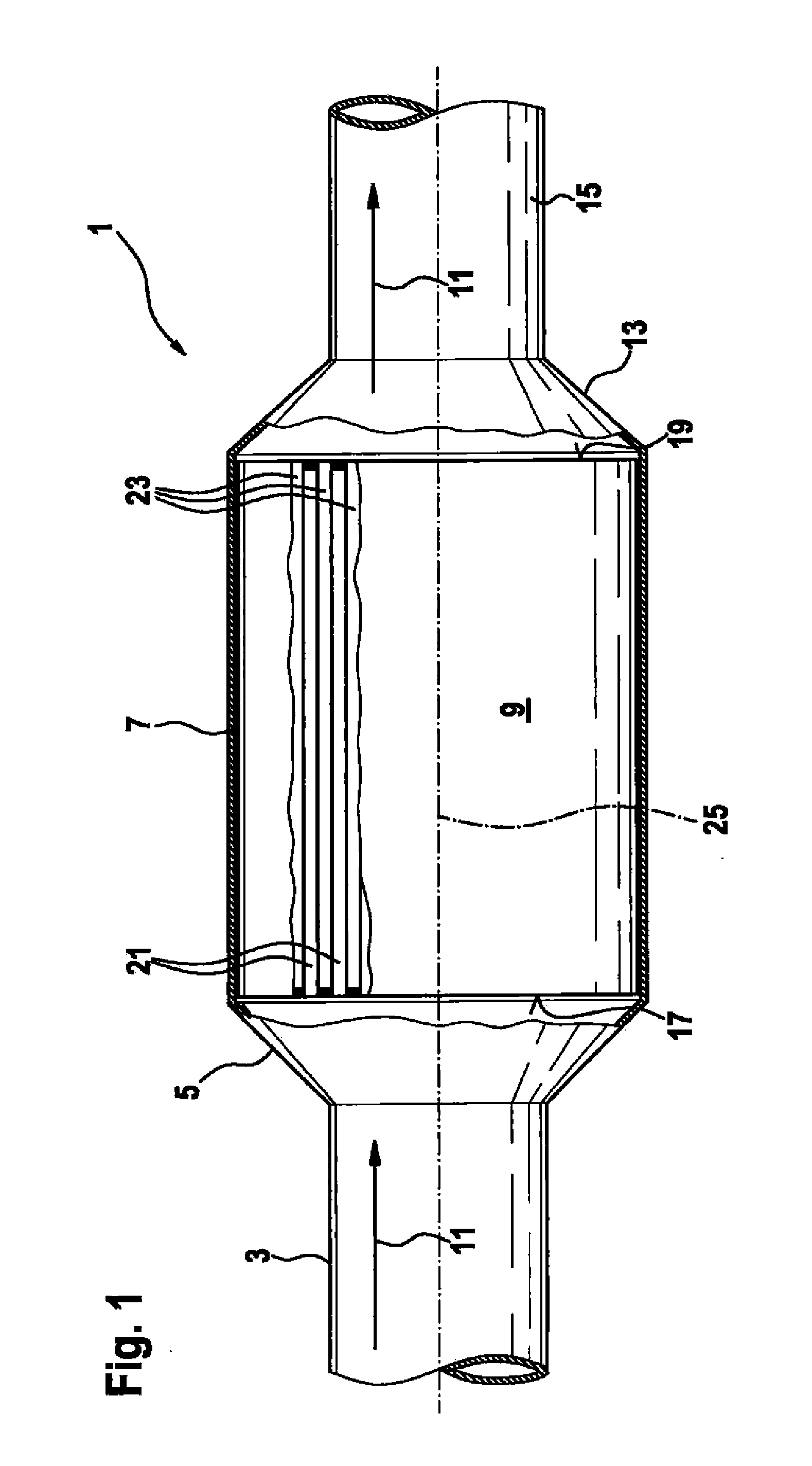
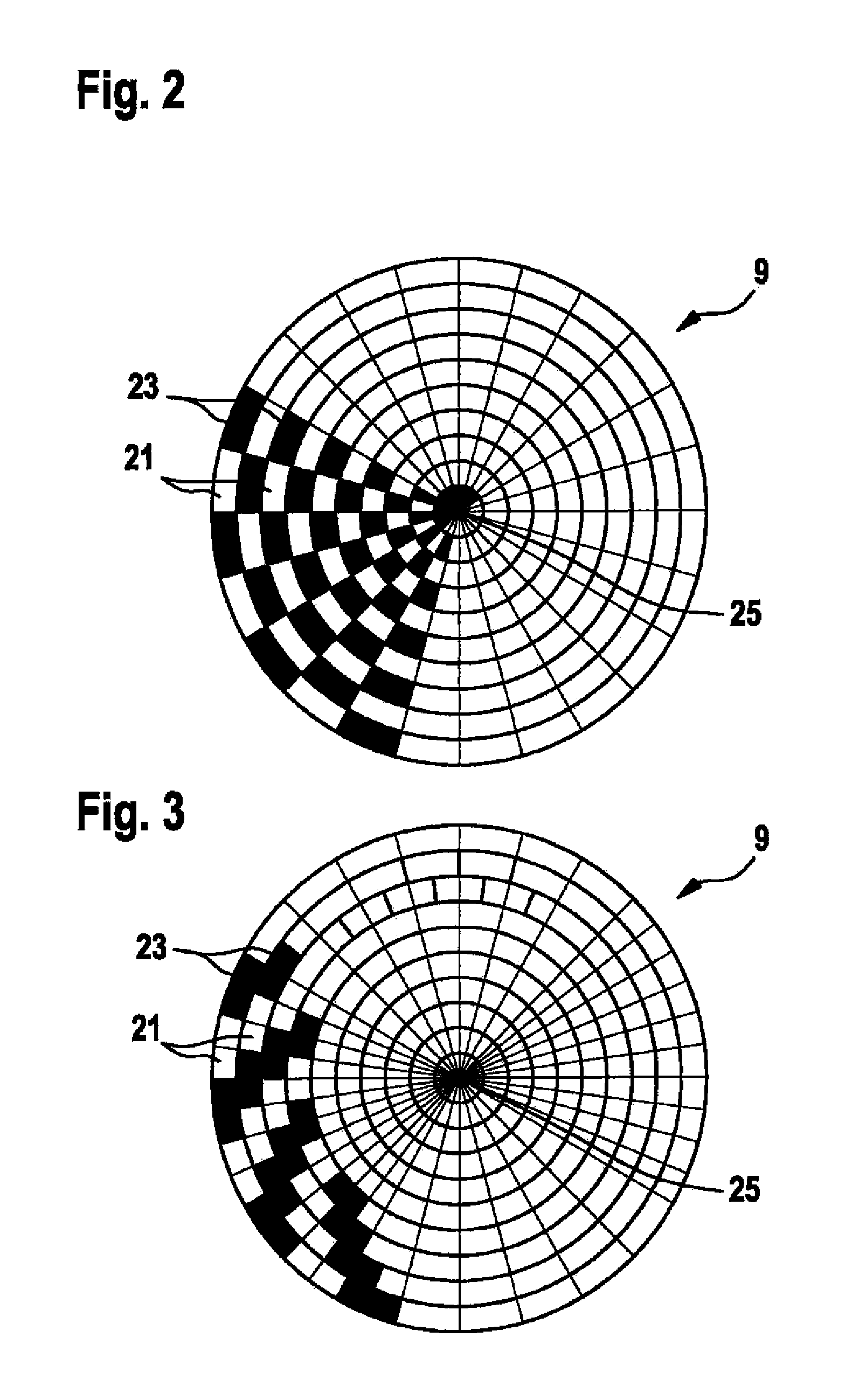
[0027]For the exhaust gas to be forced to flow through the walls (having no reference numeral) of filter element 9, inlet channels 21 are open at inlet face 17 and closed at outlet face 19. So-called outlet channels 23 are closed at inlet face 17 and open at outlet face 19. The closures of inlet channels 21 and outlet channels 23 are shown in FIG. 1 as b...


PUM

PropertyMeasurementUnit
Diameteraaaaaaaaaa
Electrical resistanceaaaaaaaaaa
Areaaaaaaaaaaa

Abstract

A filter element and a soot filter are provided, in which resistance against thermal shocks is improved due to the channel geometry.

Description

FIELD OF THE INVENTION[0001]The present invention relates to a filter element for purifying exhaust gases of an internal combustion engine. Filter elements of this type are used, for example, as soot filters for diesel engines.BACKGROUND INFORMATION[0002]The filter elements are often made of a ceramic material and have a plurality of inlet channels and outlet channels running parallel to each other.[0003]Filter elements made of ceramic materials are manufactured by extrusion. This means that the blank of the filter element is a prismatic body having a plurality of channels running parallel to each other. The channels of a blank are initially open at both ends.[0004]For the exhaust gas to be purified to flow through the walls of the filter, one group of channels is closed at the downstream end of the filter element, while another group of the channels is closed at the upstream end of the filter element. Two groups of channels are thus formed, namely the so-called inlet channels, whic...

Claims


Application Information

Patent Timeline
IPC IPC(8): F01N3/022B01D46/00
CPCB01D46/2451B01D46/2459B01D46/247B01D46/2474B01D2046/2477Y10T428/24149B01D2046/2496F01N3/0222F01N2260/10F01N2330/48Y02T10/20B01D2046/2492Y02T10/12B01D46/2488B01D46/2486B01D46/2498B01D46/24F01N3/022B01D46/2484B01D46/2496
Inventor KOMORI, TERUOREINSCH, BERNDTHUENER, LARS
Owner ROBERT BOSCH GMBH
Why Eureka
Try Eureka