Recessed LED down light

a led down light and recessed technology, applied in the direction of lighting support devices, light source combinations, instruments, etc., can solve the problems of excessive led junction temperature rise, device loss, and limit on the maximum cri of led for optimum lumen-cost performan

Inactive Publication Date: 2010-11-04
FOCAL POINT
View PDF64 Cites 81 Cited by
  • Summary
  • Abstract
  • Description
  • Claims
  • Application Information

AI Technical Summary

Benefits of technology

[0020]In another embodiment, the LED recessed down light fixture further comprises a heat sink mounted on top of the top panel of the housing. The height of the light fixture with the heat sink mounted is no more than ¼ inch taller than the height of the light fixture without the heat sink mounted. The heat sink comprises a flat member mounted to the top panel of the housing and a fin member that extends horizontally from the flat member and the front panel of the housing. Additionally, the fin member of the heat sink comprises a set of vertical fins and horizontal fins configured in a square wave pattern.
[0021]In another embodiment of the present invention, a light emitting diode (LED) circuit board connected to an AC power source and used for a recessed down light fixture comprises a plurality of resistors electrically connected to the LED circuit board, a bridge rectifier electrically connected to the LED circuit board for converting the AC power to DC power, and a plurality of at least 80 miniature LEDs electrically connected to the LED circuit board. The LEDs are configured to provide an

Problems solved by technology

This puts a limit on the maximum CRI of an LED for an optimum lumens-cost-performance.
However, LEDs, like all electronic devices, are not without losses, where heat is generated as a by-product, and needs to

Method used


Image

  • Recessed LED down light
  • Recessed LED down light
  • Recessed LED down light

Examples


Embodiment Construction

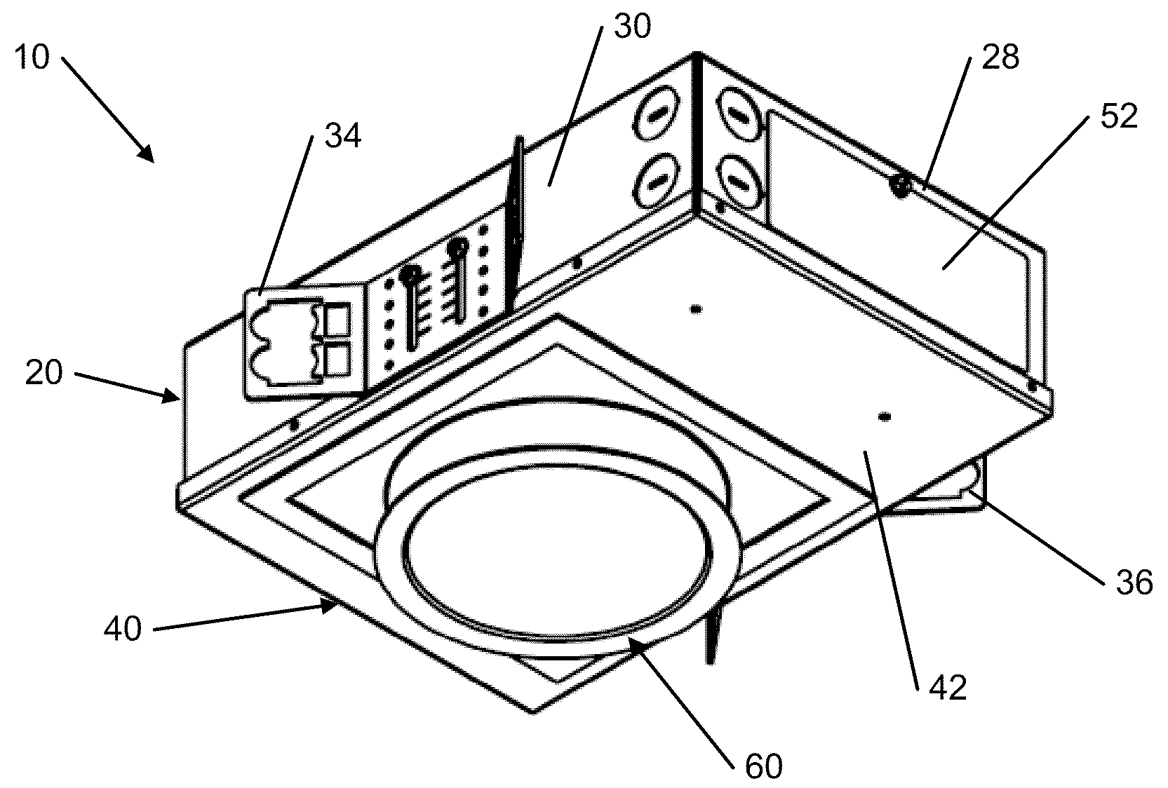
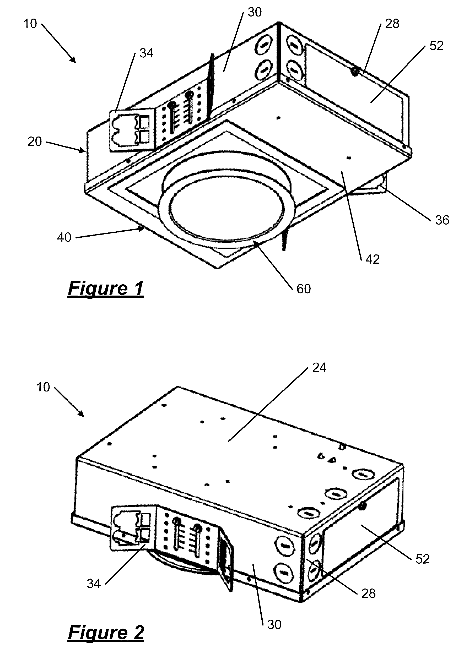
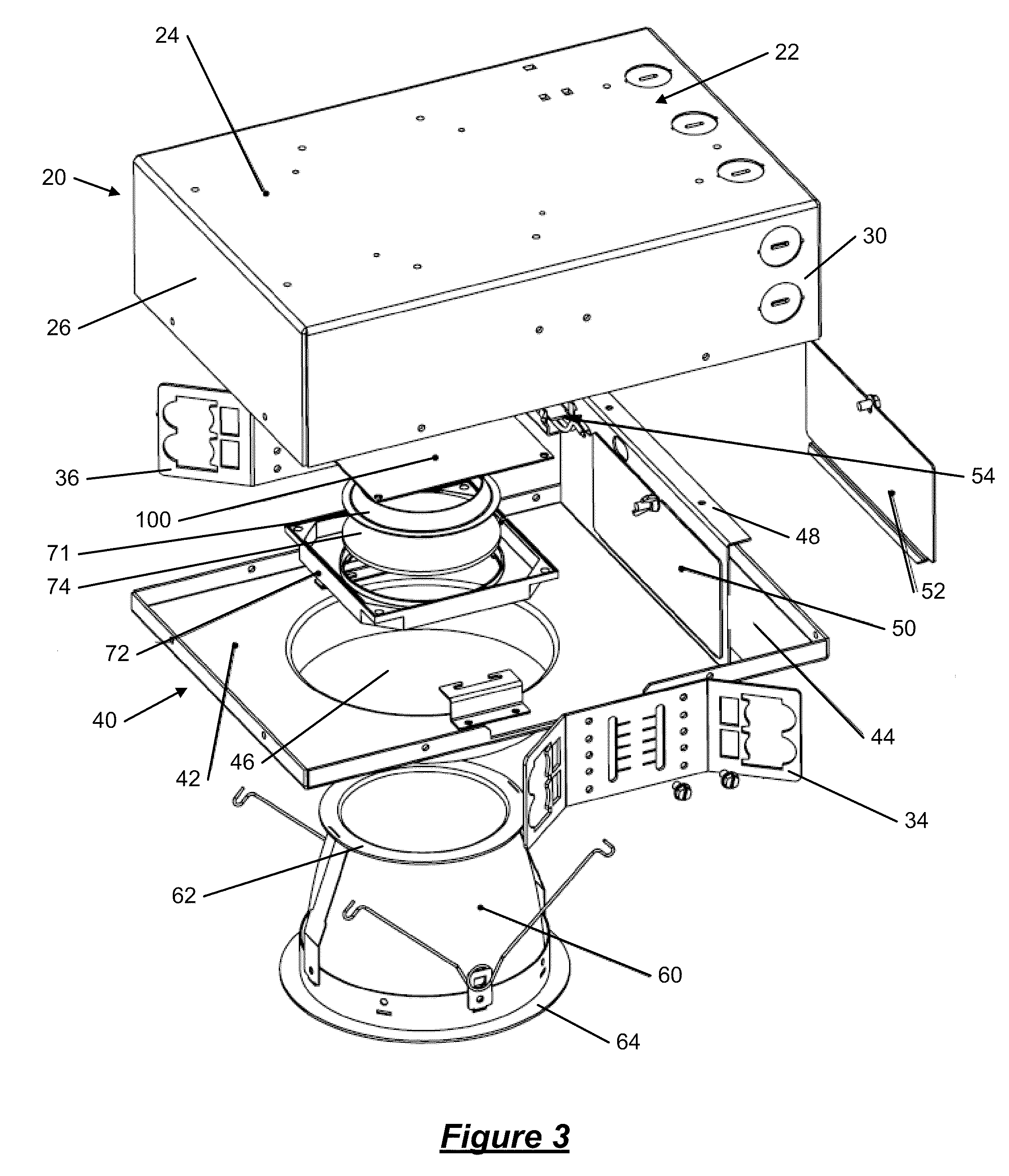
[0045]As is apparent from the Figures described above and the description provided below, various components are disclosed below and may be mounted to other components. Unless otherwise noted, mounting may be direct or indirect and this disclosure is not intended to be limiting in this respect. It is noted that various components are described below as separate components. Unless otherwise noted, two or more of these components may be combined to form a single component as appropriate and this disclosure is not intended to be limiting in this respect unless otherwise noted.

[0046]Various features are described below in greater detail. It should be noted that different combinations of these features may be combined as desired to generate LED down lights with more or less features, depending on the features that are needed. Thus, unless otherwise noted, it is envisioned that additional LED down lights using combinations of the below depicted features are potentially within the scope of...


PUM


Abstract

In an embodiment of the present invention, a light emitting diode (LED) recessed down light fixture comprises a housing, a reflector assembly mounted to the housing, and an LED circuit board attached to the housing over the reflector assembly. The LED circuit board includes a plurality of resistors electrically connected to the LED circuit board, a bridge rectifier, and a plurality of at least 80 miniature LEDs electrically connected to the LED circuit board and configured to provide light. The plurality of miniature LEDs are separated into a plurality of LED clusters. Each cluster is electrically connected to at least one resistor. Further, the plurality of miniature LEDs are arranged in a configuration such that a voltage differential across any two proximate LEDs is less than 36 volts. The down light fixture further comprises a lens cover attached to the top end of the reflector assembly.

Description

BACKGROUND OF THE INVENTION[0001]1. Field of the Invention[0002]The present invention relates to recessed light fixtures, more specifically to LEDs used in recessed down light fixtures.[0003]2. Description of Related Art[0004]Recessed light fixtures are known, and are typically used when it is desirable to minimize the projection of the light fixture below the ceiling surface. Recessed light fixtures, as opposed to light fixtures that substantially extend below the ceiling surface, tend to be more aesthetically appealing and provide a cleaner look when installed. Thus, recessed light fixtures tend to be used in commercial settings such as offices and the like.[0005]Light emitting diodes (LEDs) have been used since the early 1970s as a reliable low energy light source for indicator lights. LEDs are generally single frequency light sources, but in the early 1990s, blue LEDs were introduced, which made it possible to generate white light by coating the blue LED die with phosphor. The f...

Claims


Application Information

Patent Timeline
IPC IPC(8): F21V21/00H05B37/02H01J9/00
CPCF21K9/00F21S8/026F21V23/005F21V29/004F21V29/2212F21Y2105/001F21Y2113/005H05B33/0803H05K1/181Y02B20/348F21Y2101/02F21Y2105/10F21Y2115/10F21Y2113/13F21V29/767F21V29/763Y02B20/30H05B45/30
Inventor JANIK, RAYMONDYUEN, STEPHEN H.THORNTON, MICHAEL T.DOUBEK, DAVID E.THORNTON, JR., PETER F.
Owner FOCAL POINT
Why Eureka
Try Eureka