Communication outlet identification system using ethernet signals

a communication outlet and ethernet signal technology, applied in the field of communication outlet identification system using ethernet signal, can solve the problems of accurate network documentation collection and maintenance, and achieve the effect of relatively low frequency range used for communication in the ac common-mode backchannel signaling system

Inactive Publication Date: 2010-11-11
PANDUIT
View PDF5 Cites 0 Cited by
  • Summary
  • Abstract
  • Description
  • Claims
  • Application Information

AI Technical Summary

Benefits of technology

[0004]According to one embodiment of the present invention, an AC common mode backchannel signaling system is used for identifying outlets in a communications network. Such a system can be employed in an Ethernet network, and the frequency range used for communication in the AC common-mode backchannel signaling system is relatively low compared to the frequency range used for network communications.

Problems solved by technology

One of the challenges faced by IT network managers is the collection and maintenance of accurate network documentation.

Method used


Image

  • Communication outlet identification system using ethernet signals
  • Communication outlet identification system using ethernet signals
  • Communication outlet identification system using ethernet signals

Examples


Embodiment Construction

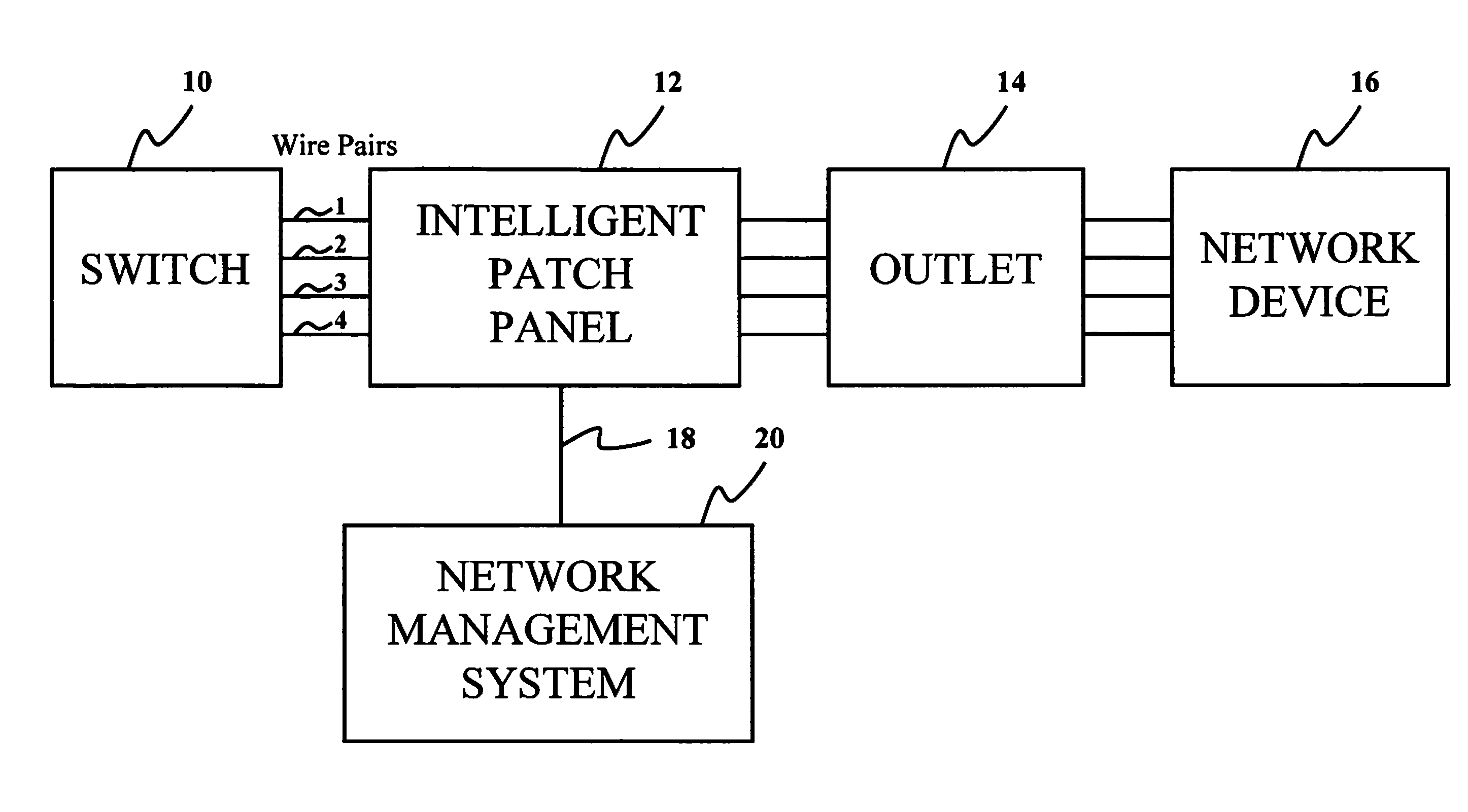
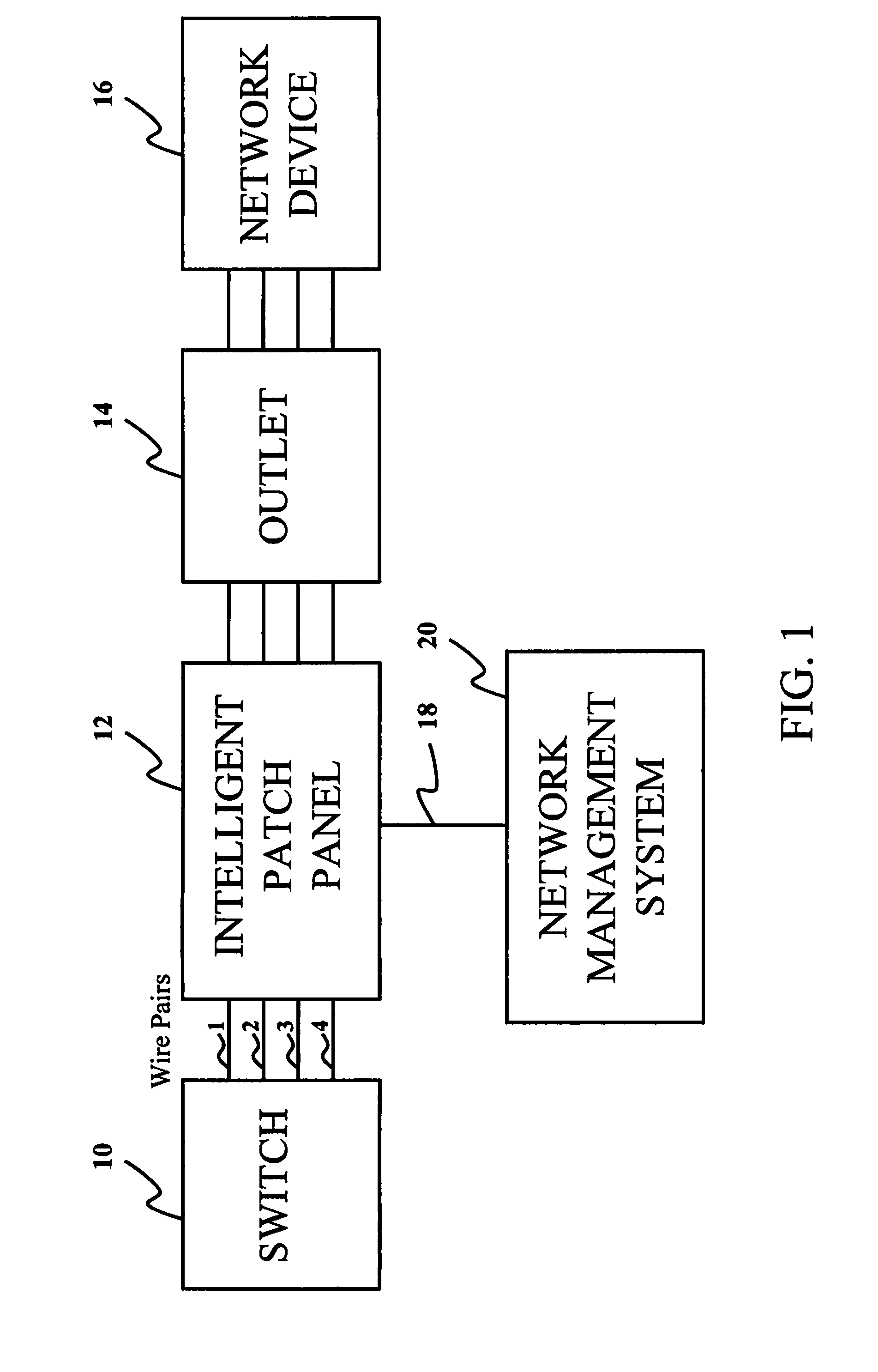
[0010]FIG. 1 is a block diagram showing system elements in a communication outlet identification system according to one embodiment of the present invention. Four wire pairs 1, 2, 3, and 4 are used for communications between network elements. A network switch 10 is connected via the wire pairs 1-4 to an intelligent patch panel 12. The intelligent patch panel 12, in turn, is connected to a communication outlet 14 via the wire pairs. The communication outlet 14 is connected to a network device 16. Examples of network devices include VOIP phones, computers, and other network end-user devices. The intelligent patch panel 12 is connected via a management link 18 to a network management system 20.

[0011]FIG. 1 shows only one communication pathway in a network, but it is to be understood that there may be several network devices, connected via several outlets, to a single intelligent patch panel 12. Further, more than one intelligent patch panel 12 may be connected to a switch 10. According...


PUM


Abstract

An AC common mode backchannel signaling system is used to provide outlet ID information in a communication network. Wire pairs of a communication network are used to support the AC common mode backchannel signaling system, while also supporting Ethernet communications as well as Power Over Ethernet (PoE). Query and receiving AC circuitry is provided in an intelligent patch panel, and outlet ID receiving and response AC circuitry is provided in communication outlets. These two sets of AC circuitry use the AC common mode backchannel signaling system to communicate with one another, without disrupting PoE or Ethernet signaling on the wire pairs of the network.

Description

RELATED APPLICATION[0001]The present application incorporates by reference in its entirety U.S. patent application Ser. No. 11 / 265,316, entitled “Method and Apparatus for Patch Panel Patch Cord Documentation and Revision,” filed Nov. 2, 2005.BACKGROUND OF THE INVENTION[0002]One of the challenges faced by IT network managers is the collection and maintenance of accurate network documentation. Technologies such as Voice Over Internet Protocol (VOIP) have increased the importance of finding the identity and location of network devices (for example, in emergency situations). At the same time, it has grown more common for network devices to be powered by the communication network itself. Power Over Ethernet (PoE) is an example of this technology.[0003]It is desirable to have systems and methods that can determine the location of network devices, while also allowing the provision of power over network cabling. It is further desirable for such a system to be compatible with PoE systems tha...

Claims


Application Information

Patent Timeline
Patent Type & Authority Applications(United States)
IPC IPC(8): G01R19/00
CPCH04L12/10
Inventor CAVENEY, JACK E.NORDIN, RONALD A.
Owner PANDUIT
Why Eureka
Try Eureka