Passive component

a passive component and component technology, applied in waveguide devices, waveguide type devices, electrical devices, etc., can solve problems such as unwanted peak in attenuation range, and achieve the effects of improving performance, large attenuation level, and sharp attenuation characteristics

Active Publication Date: 2009-05-28
SOSHIN ELECTRIC
View PDF4 Cites 3 Cited by
  • Summary
  • Abstract
  • Description
  • Claims
  • Application Information

AI Technical Summary

Benefits of technology

[0025]According to the present invention, in particular, the unbalanced to balanced converter is disposed in an upper region of the dielectric substrate along the stacking direction of the dielectric layers, and the filter is disposed in a lower region of the dielectric substrate along the stacking direction of the dielectric layers. Therefore, the passive component, with the filter and the unbalanced to balanced converter being integrally combined in the dielectric substrate, can exhibit a large attenuation level in a blocking range, so as to provide sharp attenuation characteristics for improved performance.
[0026]The dielectric layers of the dielectric substrate may comprise dielectric materials of different types. Since the dielectric layers are stacked, a dielectric layer having a high dielectric constant may be used where a strong electromagnetic coupling is provided, and a dielectric layer having a low dielectric constant may be used where a weak electromagnetic coupling is provided. By using materials having desired dielectric constants, freedom with respect to thickness is increased, thereby enabling a low-profile passive component.
[0027]For example, the dielectric constant of the dielectric layers of the filter may be higher than the dielectric constant of the dielectric layers utilized in the unbalanced to balanced converter. The electrode area of the filter can thus be reduced, in order to decrease stray coupling in the unbalanced to balanced converter.
[0028]The passive component according to the present invention has a simple structure, is capable of adjusting attenuation characteristics in a low range of frequency characteristics, and can be used in various environments.

Problems solved by technology

If the output stage of the filter and the input stage of the unbalanced to balanced converter are directly connected to each other, then the filter and the unbalanced to balanced converter cause unwanted matching in an attenuation range of the pass characteristics, thereby producing an unwanted peak in the attenuation range.

Method used


Image

  • Passive component
  • Passive component
  • Passive component

Examples


Embodiment Construction

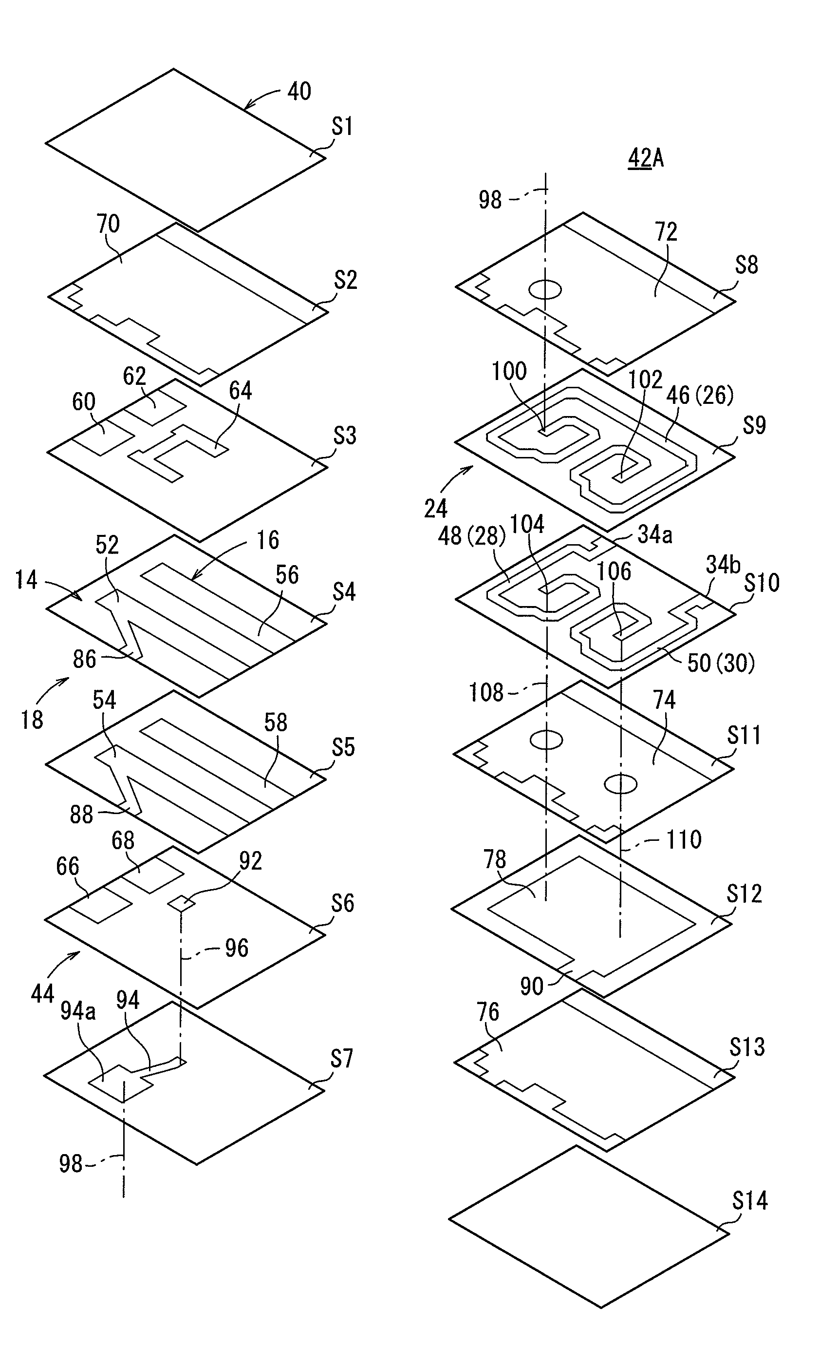
[0038]A passive component according to an embodiment of the present invention shall be described below with reference to FIGS. 1 through 8.

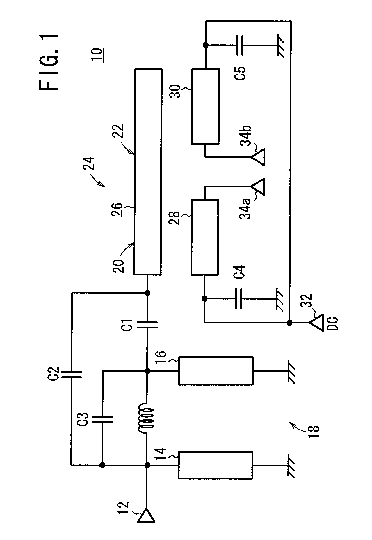
[0039]As shown in FIG. 1, the passive component 10 according to the embodiment comprises a filter 18 according to an unbalanced input / unbalanced output system, having an input resonator 14 connected to an unbalanced input terminal 12, an output resonator 16 coupled to the input resonator 14, and an unbalanced to balanced converter (hereinafter referred to as “converter”) 24 having two coupling dual-lines (a first coupling dual-line 20 and a second coupling dual-line 22).

[0040]The output stage of the filter 18 and the input stage of the converter 24 are connected to each other by a first capacitor C1. The input stage of the filter 18 and the input stage of the converter 24 are connected to each other by a second capacitor C2. The second capacitor C2 functions as a jump capacitor.

[0041]The converter 24 has a first line 26, a second line 28, and a t...


PUM


Abstract

A passive component is provided with a filter section employing a nonequilibrium input/output system, which has an input side resonator connected to a nonequilibrium input terminal, and an output side resonator coupled with the input side resonator; and a converting section having two double line coupled lines. An output stage of the filter section is connected with an input stage of the converting section through a first capacitor, and an input stage of the filter section is connected with the input stage of the converting section through a second capacitor. Namely, the second capacitor functions as a jump capacitor. The position of an attenuation pole is permitted to be adjusted by a second capacitor in a region low in frequency characteristics.

Description

TECHNICAL FIELD[0001]The present invention relates to a passive component such as a multilayered dielectric filter for resonant circuits for use in a microwave band ranging from several hundred MHz to several GHz, and more particularly to a passive component which is effective to make communication devices and electronic devices small in size.BACKGROUND ART[0002]Recently, semiconductor components such as ICs have become highly integrated and have quickly become smaller in size. Passive components such as filters for use with semiconductor devices have also become smaller in size. Multilayered dielectric filters employing dielectric substrates are effective to make passive components smaller in size (see, for example, Patent Documents 1 and 2).[0003]Generally, it has been proposed to integrally combine a filter and an unbalanced to balanced converter in a dielectric substrate (see, for example, Patent document 3).[0004]Passive components for use in different environments are classifi...

Claims


Application Information

Patent Timeline
Patent Type & Authority Applications(United States)
IPC IPC(8): H03H5/00
CPCH01P1/203H01P5/10H01P1/20345
Inventor KIMURA, HIRONOBUHIRAI, TAKAMIMIZUTANI, YASUHIKOTAKEUCHI, HIROTAKA
Owner SOSHIN ELECTRIC
Why Eureka
Try Eureka