Air cleaner for internal combustion engine

a technology for air cleaners and internal combustion engines, which is applied in the direction of air cleaners for fuel, charge feed systems, and non-fuel substance addition to fuel, etc. it can solve the problem that conventional air cleaners with the above described sound absorbing material or sound absorbing layer cannot readily reduce the low frequency components, and achieve the effect of reducing components and low frequency range of intake nois

Active Publication Date: 2019-10-29
TOYOTA BOSHOKU KK
View PDF21 Cites 1 Cited by
  • Summary
  • Abstract
  • Description
  • Claims
  • Application Information

AI Technical Summary

Benefits of technology

[0005]Accordingly, it is an objective of the present invention to provide an air cleaner for an internal combustion engine that effectively reduces components of a low frequency range of intake noise.

Problems solved by technology

However, conventional air cleaners having the above described sound absorbing material or sound absorbing layer cannot readily reduce the low frequency components.

Method used


Image

  • Air cleaner for internal combustion engine
  • Air cleaner for internal combustion engine
  • Air cleaner for internal combustion engine

Examples


Embodiment Construction

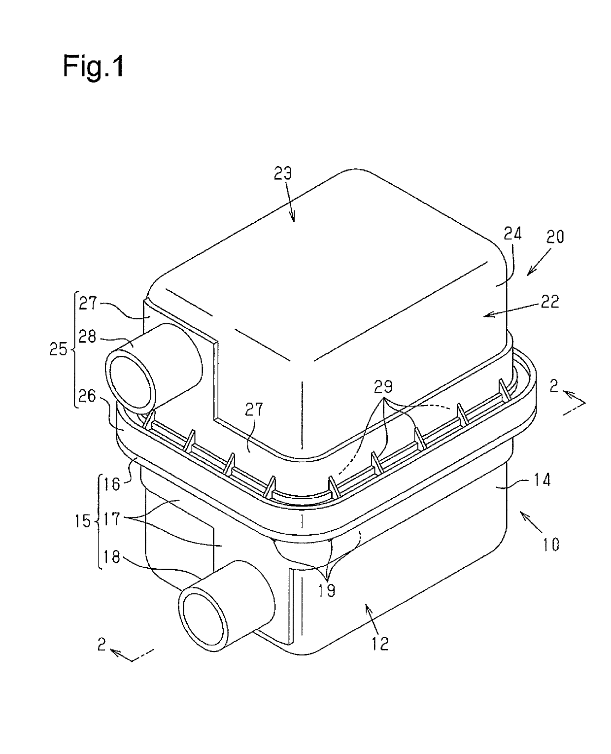
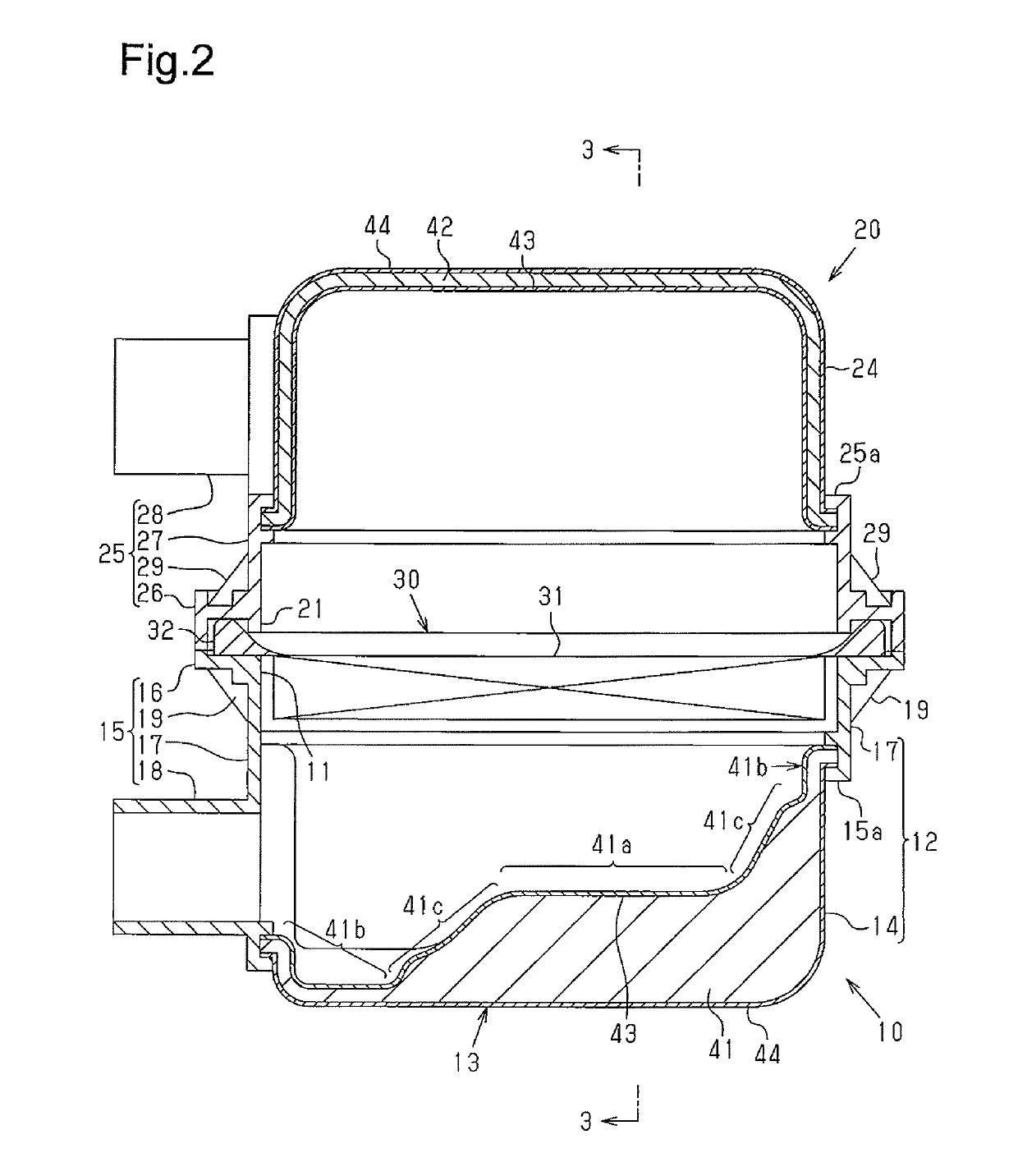
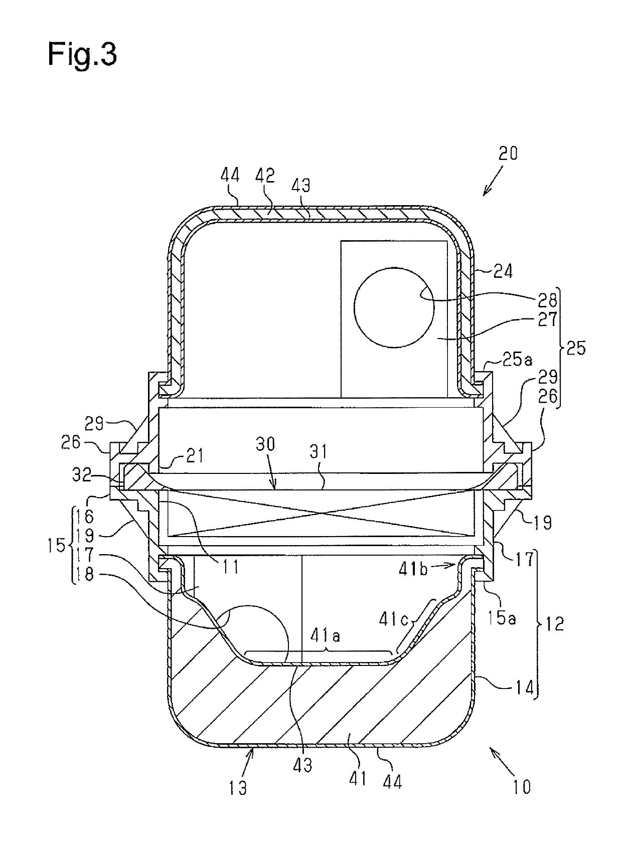
[0014]One embodiment will now be described with reference to FIGS. 1 to 3.

[0015]An air cleaner shown in FIGS. 1 to 3 is arranged in an intake passage of a vehicle-mounted internal combustion engine and includes a first housing 10 having a cylindrical inlet 18 and a second housing 20 having a cylindrical outlet 28.

[0016]As shown in FIGS. 2 and 3, the first housing 10 includes a peripheral wall 12, which surrounds an upper opening 11, and a bottom wall 13. An outward extending flange 16 is provided around the entire periphery of the upper opening 11. The inlet 18 protrudes from the outer surface of the peripheral wall 12.

[0017]The second housing 20 has a peripheral wall 22, which surrounds a lower opening 21, and a top wall 23. An outward extending flange 26 is provided around the entire periphery of the lower opening 21. The outlet 28 protrudes from the outer surface of the peripheral wall 22.

[0018]A filter element 30 is arranged between the upper opening 11 of the first housing 10 a...


PUM


Abstract

An air cleaner for an internal combustion engine includes a first housing having an inlet and an upper opening, a second housing having an outlet and a lower opening, a filter element arranged between the upper opening of the first housing and the lower opening of the second housing. The first housing includes a sound reducing wall portion. The sound reducing wall portion has a sound absorbing layer, which is made of nonwoven fabric, and an inner covering layer, which is fixed to the inner surface of the sound absorbing layer and made of a material having a lower air permeability than that of the sound absorbing layer.

Description

BACKGROUND OF THE INVENTION[0001]The present invention relates to an air cleaner for an internal combustion engine.[0002]Conventionally, an air cleaner for a vehicle-mounted internal combustion engine has a first housing having an inlet and an opening, a second housing having an outlet and an opening, a filter element arranged between the opening of the first housing and the opening of the second housing.[0003]The wall portion of the housing of the air cleaner described in Japanese Laid-Open Patent Publication No. 2002-21660 is formed by sound absorbing material composed of filter paper, nonwoven fabric, or porous material such as open-cell sponge. The inner wall surface of the housing of the air cleaner described in Japanese Laid-Open Utility Model Publication No. 64-11359 is constituted by a sound absorbing layer such as foamed polyurethane. In these air cleaner, the sound absorbing material reduces intake noise.[0004]The present inventors discovered that, in an air cleaner, the s...

Claims


Application Information

Patent Timeline
Patent Type & Authority Patents(United States)
IPC IPC(8): F02M35/14F02M35/02F02M35/024F02M35/12
CPCF02M35/02425F02M35/1272F02M35/0201F02M35/14F02M35/02491F02M25/08
Inventor KIMURA, RYUSUKEINUZUKA, YOSHINORI
Owner TOYOTA BOSHOKU KK
Why Eureka
Try Eureka