Heat dissipation device

Inactive Publication Date: 2010-11-18
HONG FU JIN PRECISION IND (SHENZHEN) CO LTD +1
5 Cites 2 Cited by

AI-Extracted Technical Summary

Problems solved by technology

If the performance of the heat dissipation device is not good, the bridge chip may be overheated and damaged.
However, different bridge chips usually require different heat...

Abstract

A heat dissipation device includes a plate, a protrusion to divide a top of the plate into a number of mounting areas, and a number of heat sinks selectively received on the number of mounting areas.

Application Domain

Semiconductor/solid-state device detailsSolid-state devices +2

Technology Topic

Heat spreaderComputer engineering

Image

  • Heat dissipation device
  • Heat dissipation device
  • Heat dissipation device

Examples

  • Experimental program(1)

Example

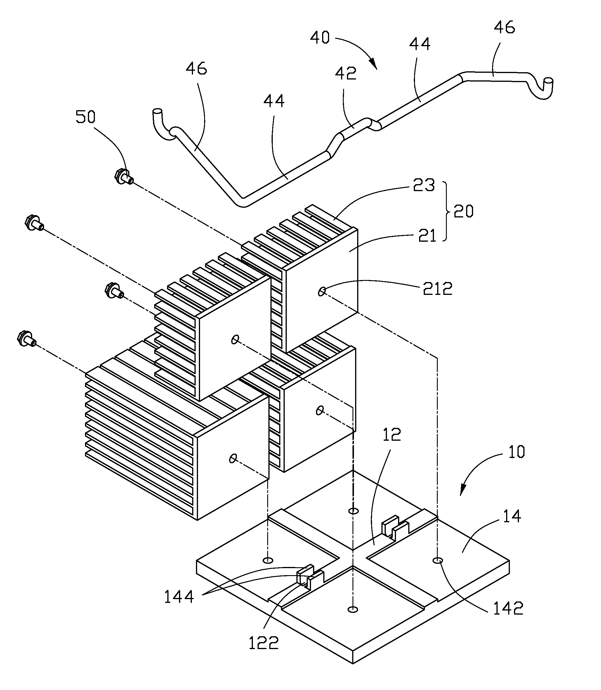
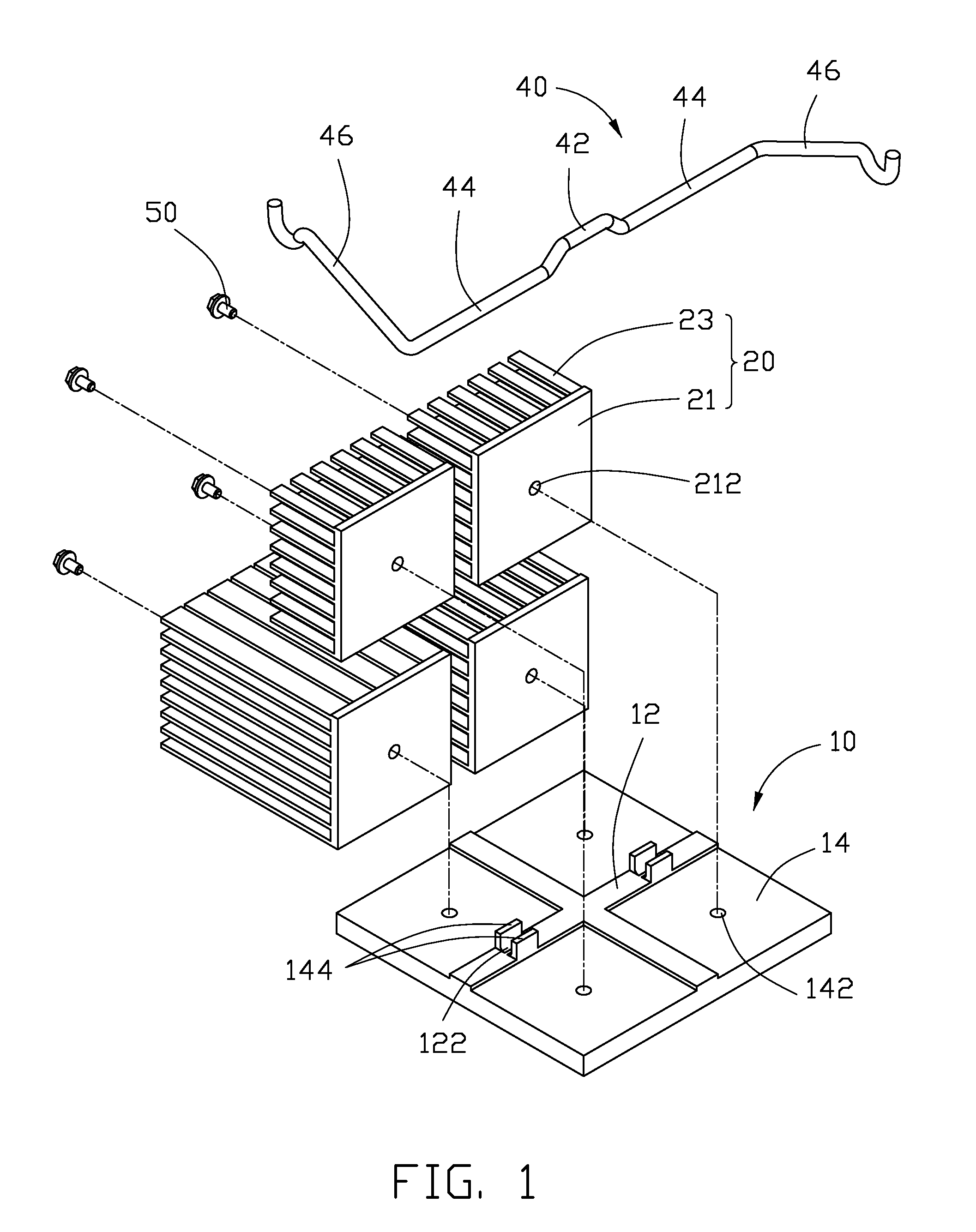
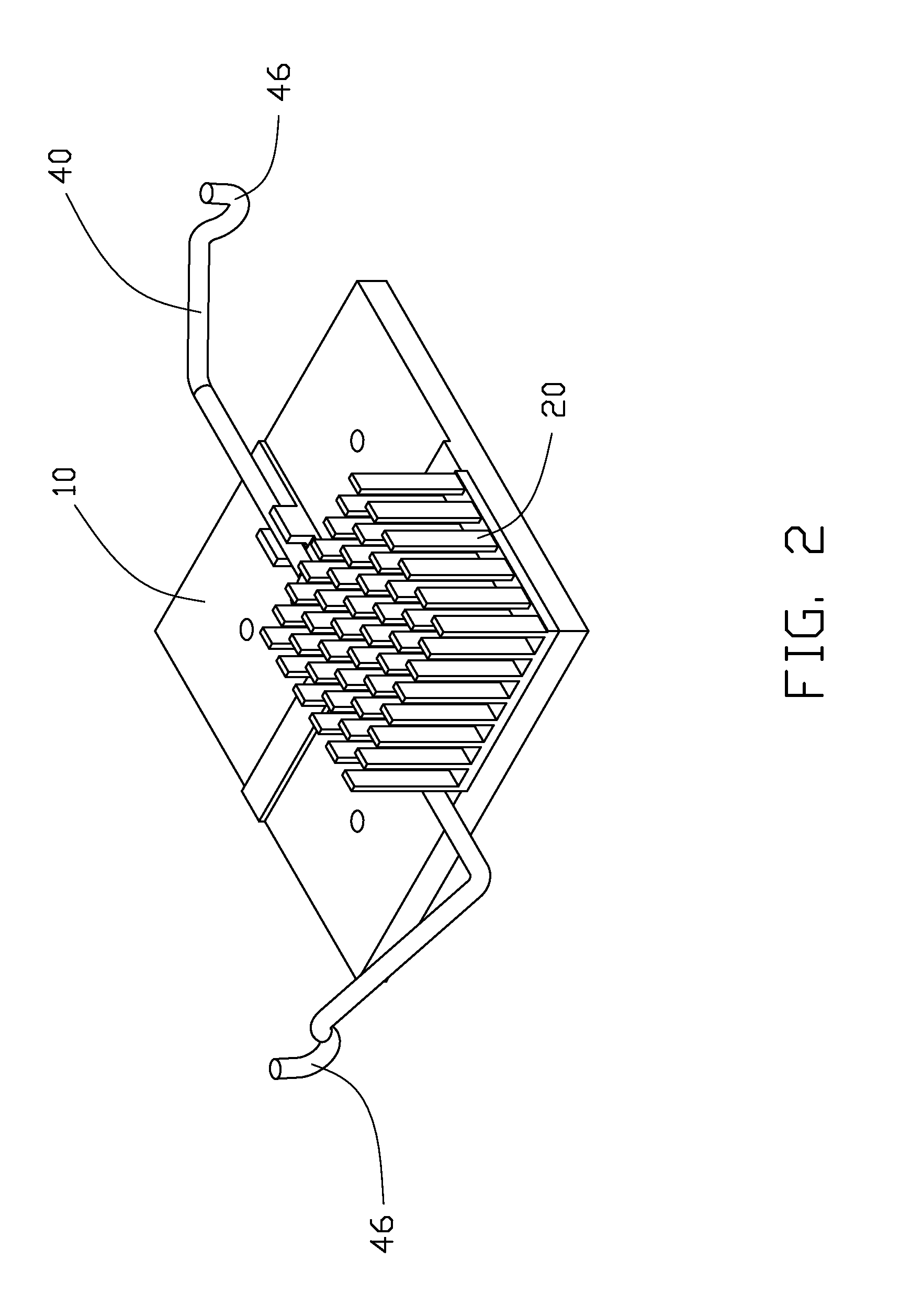
[0009]Referring to FIG. 1, an exemplary embodiment of a heat dissipation device includes a square plate 10 to be located on a top of an electronic element, such as a bridge chip of a circuit board. Four heat sinks 20 mounted on the plate 10 to absorb heat from the electronic element. A clip 40 made of resilient material to fix the plate 10 on the circuit board, and four fasteners 50, such as four screws, to mount the heat sinks 20 to the plate 10.
[0010]Each heat sink 20 includes a base 21 and a plurality of parallel fins 23 extending perpendicular from the base 21. A fixing hole 212 is defined in a center of the base 21. In one embodiment, the bases 21 of the heat sinks 20 are the same, while heights of the plurality of fins 23 of each heat sink 20 differ. Size of the base 21 and height of the plurality of fins 23 of each heat sink 20 can be predetermined according to need. The number of the heat sinks 20 can be selected according to heat dissipation requirement of the electronic element.
[0011]A cross-shaped protrusion 12 protrudes from a center of a top of the plate 10, to divide the top of the plate 10 into four mounting areas 14, each for a single heat sink 20. Sizes of the mounting areas 14 are the same. A locking hole 142 is defined in a center of each mounting area 14, corresponding to the fixing hole 212 of a corresponding heat sink 20. Two pairs of tabs 144 extend perpendicular from the protrusion 12. Two of each pair of tabs 144 are opposite to each other. A latching portion 122 is formed between the tabs of each pair of tabs 144. In other embodiments, the plate 10 may be divided into three mounting areas by the protrusion 12 of another shape.
[0012]The clip 40 includes a positioning portion 42, two resisting portions 44 extending in opposite directions from opposite ends of the positioning portion 42, and two clasping portions 46 extending from distal ends of the resisting portions 44 respectively, away from the positioning portion 42. The resisting portions 44 are fixed in the latching portions 122, to resist the protrusion 12 of the plate 10.
[0013]Referring to FIGS. 2 and 3, in use, when power for the electronic element is low, a few heat sinks 20, such as a heat sink 20 can be mounted on a corresponding mounting area 14 of the plate 10. A fastener 50 passes through the fixing hole 212 of the heat sink 20 to engage the locking hole 142 of the mounting area 14 to fix the heat sink 20 to the plate 10. When power for the electronic element is high, an increased number of the heat sinks 20, such as four, can be mounted on the mounting areas 14 of the plate 10, respectively. Four fasteners 50 pass through the corresponding fixing holes 212 of the heat sinks 20 to engage the corresponding locking holes 142 of the mounting areas 14 to fix the four heat sinks 20 to the plate 10. The clasping portions 46 of the clip 40 engage the circuit board to fix the heat dissipation device to the circuit board.
[0014]The heat sinks 20 can be selectively mounted on the plate 10, and the number and shapes of the heat sinks 20 can be selected according to heat dissipation requirement for different chips. The plate 10 is divided into a plurality of mounting areas by the protrusion 12, for fixing a plurality of the heat sinks 20 on the plate 10. The heat dissipation device can satisfy different heat dissipation requirements for different chips of the circuit board. Therefore, the heat dissipation device is cost and time saving.
[0015]The foregoing description of the exemplary embodiments of the disclosure has been presented only for the purposes of illustration and description and is not intended to be exhaustive or to limit the disclosure to the precise forms disclosed. Many modifications and variations are possible in light of the above teaching. The embodiments were chosen and described in order to explain the principles of the disclosure and their practical application so as to enable others skilled in the art to utilize the disclosure and various embodiments and with various modifications as are suited to the particular use contemplated. Alternately embodiments will become apparent to those skilled in the art to which the present disclosure pertains without departing from its spirit and scope. Accordingly, the scope of the present disclosure is defined by the appended claims rather than the foregoing description and the exemplary embodiments described therein.

PUM

no PUM

Description & Claims & Application Information

We can also present the details of the Description, Claims and Application information to help users get a comprehensive understanding of the technical details of the patent, such as background art, summary of invention, brief description of drawings, description of embodiments, and other original content. On the other hand, users can also determine the specific scope of protection of the technology through the list of claims; as well as understand the changes in the life cycle of the technology with the presentation of the patent timeline. Login to view more.
Why Eureka
Try Eureka