LED work light

a technology of led work light and led filament, which is applied in the direction of electric lighting without self-contained power, lighting heating/cooling arrangement, protective devices for lighting, etc., can solve the problems of fluorescent work light bulb breakage, bulb or filament breakage, bulb breaking with hot filament, etc., to preserve useful working life, high power, and the effect of saving the useful working li

Active Publication Date: 2005-12-01
ALLTEMP PROD CO LTD
View PDF65 Cites 232 Cited by
  • Summary
  • Abstract
  • Description
  • Claims
  • Application Information

AI Technical Summary

Benefits of technology

[0010] In a second aspect the invention provides a work light having a high power LED that requires a heatsink for operation in a normal working environment while preserving a useful life in prolonged use, an optic associated with the LED such that a beam width of light radiating from the LED is changed by the optic, and light emitting from the optic has a useful beam width of light adequate for use in working for prolonged periods, a heatsink for use with the LED to preserve useful working life of the LED when operated in prolonged use, a casing substantially enclosing the LED and optic, and the casing housing the heatsink, and a transparent cover in the casing through which the beam of light from the optic can escape the casing along a beam axis.
[00

Problems solved by technology

Incandescent work lights have been in use, but they have some drawbacks.
One drawback is that work lights are all too often dropped or knocked down and fall onto a hard surface, and this often results in breakage of the bulb or its filament.
An additional drawback of incandescent work lights is a safety hazard that results from the possibility of the bulb breaking with its hot filament in close proximity to flammable material such as spilled flammable liquid if the work light suffers a fall.
However, fluorescent work lights can experience breakage of their bulbs if they suffer a fall.
Although breakage of an operating fluorescent bulb is not as likely to ignite nearby flammable materials as breakage of an incandescent bulb is, there is still a slight chance that a fluorescent bulb can ignite adjacent flammable materials if broken while oper

Method used


Image

  • LED work light
  • LED work light
  • LED work light

Examples


Embodiment Construction

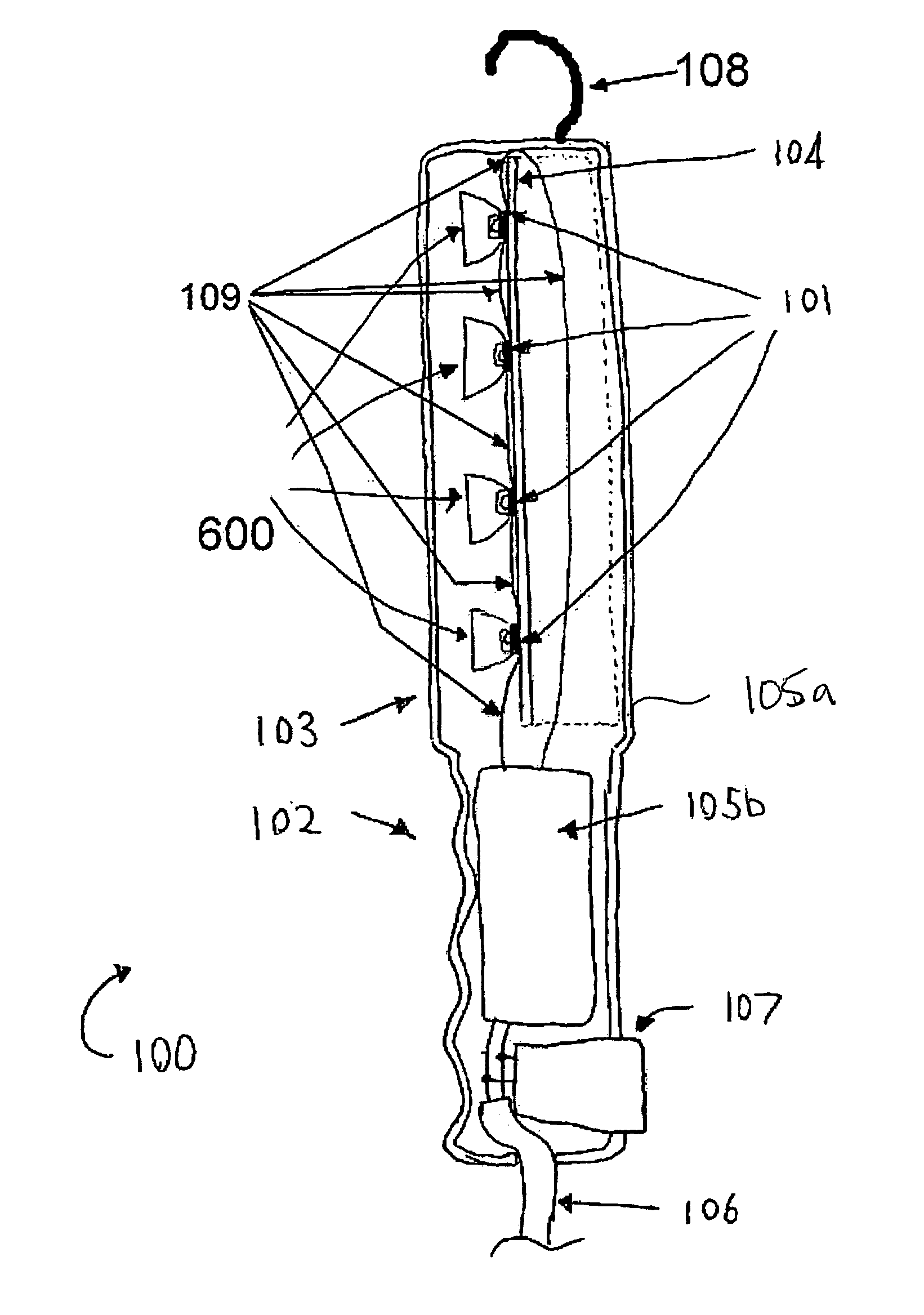
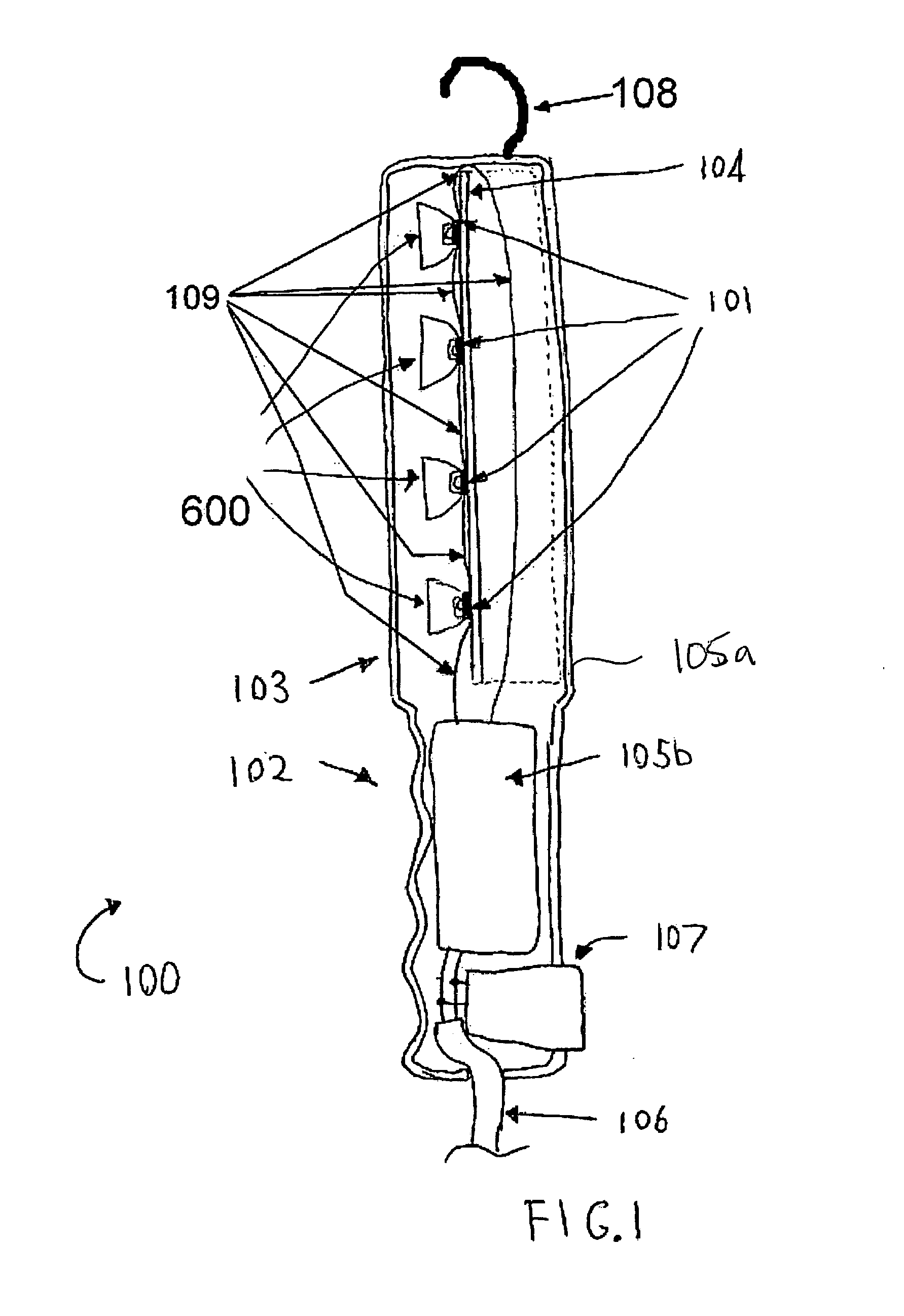
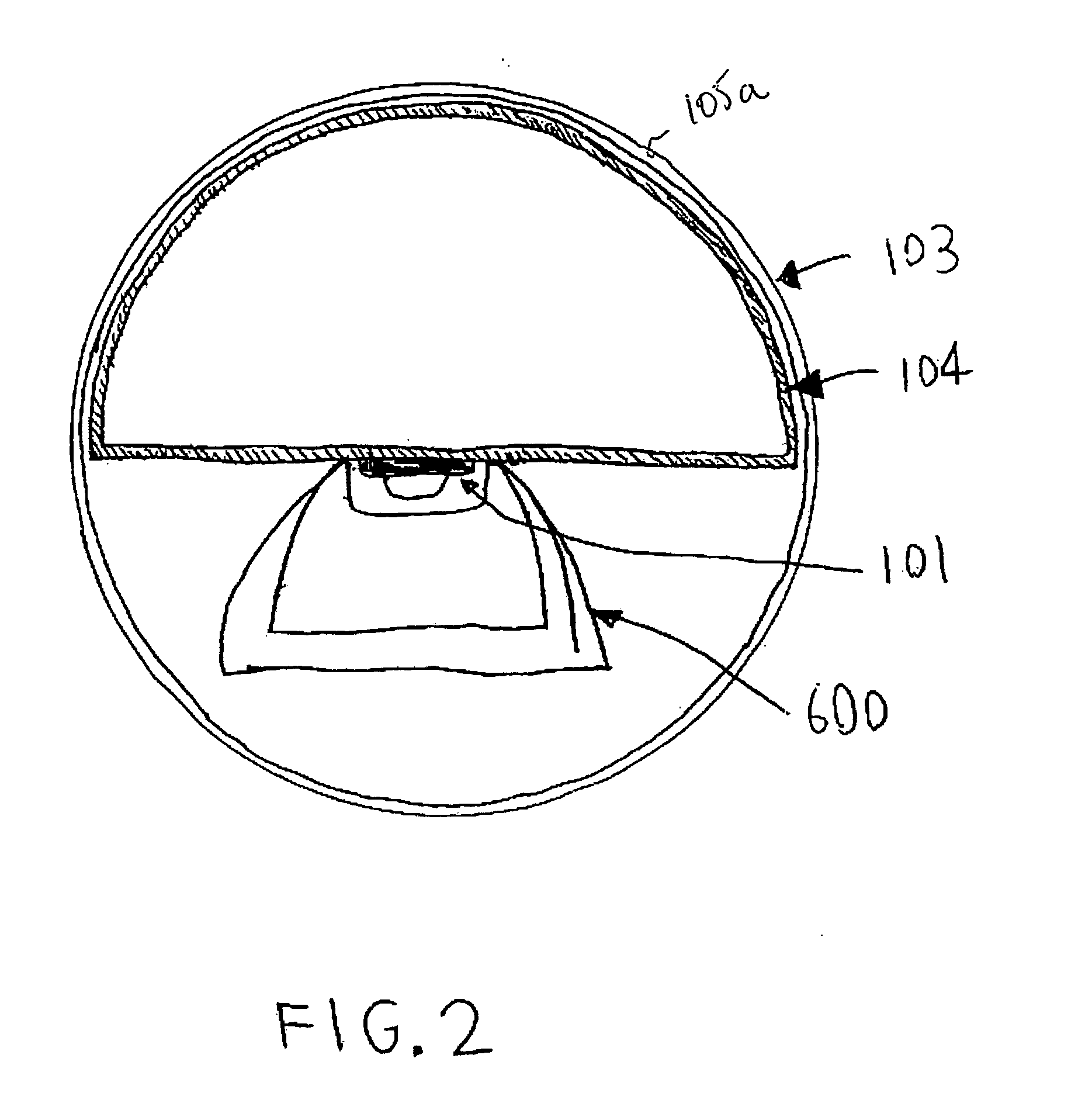
[0099] Referring to FIGS. 1 and 2, a work light 100 has a handle 102 and a light head 103 that houses an LED heatsink 104. The LED heatsink 104 has LEDs 101 mounted on it. The LED heatsink 104 as shown is in the shape of a semicircular tube, which may or may not be constructed of a single piece of metal. The semicircular shape (best evident in FIG. 2) permits the heatsink 104 to be in contact with or very close to the structural material of the light head 102 so that heat can more easily escape into the environment through the structural material of the light head 102. Alternatively, the heatsink 104 may be of a different shape or more than one heatsink may be used.

[0100] The handle 102 and the light head 103 may be comprised in a single outer casing 105a. Such a single outer casing 105a may be tubular in shape and made of transparent plastic such as acrylic or polycarbonate. Such a tubular outer casing 105a may have a semicircular tube shaped version of the heatsink 104 contained ...


PUM


Abstract

Work light has LEDs that require heatsink. Desired radiation pattern achieved by using optical components designed to produce beam or LEDs may have beams in different directions. Radiation pattern of LEDs may be changed by refractive-reflective optics or by convex lenses. Convex lenses may be hemispheres, other planoconvex shapes, concavo-convex shapes, or other shapes. Curved surfaces on any lenses may be spherical or aspheric. Ballast to operate the LEDs from line voltage AC or low voltage DC. Work light may contain batteries. The work light may be mounted on a stand. May have accessory mount. May have charging station. May have a paging transmitter to activate a paging receiver in work light. May have openings for heat transfer from heatsink to ambient air external to light.

Description

CROSS-REFERENCE TO RELATED APPLICATIONS [0001] This application claims the benefit of the filing date of U.S. Patent Application No. 60 / 521,240 filed 18 Mar. 2004, Application No. 60 / 521,680 filed 16 Jun. 2004, Application No. 60 / 521,689 filed 17 Jun. 2004, Application No. 60 / 521,738 filed 28 Jun. 2004, and Application No. 60 / 521,888 filed 17 Jul. 2004 under the title LED Work Light. The content of the above applications is hereby expressly incorporated by reference into the detailed description hereof.FIELD OF THE INVENTION [0002] The application relates to work lights. More particularly it relates to LED work lights. BACKGROUND OF THE INVENTION [0003] Work lights, often known as “trouble lights”, are widely used in automotive repair shops and other repair settings and construction settings. Such work lights are often in a form that can alternatively be handheld or hung from a suitable elevated object such as a raised automobile hood. [0004] Incandescent work lights have been in us...

Claims


Application Information

Patent Timeline
IPC IPC(8): F21L4/00F21L14/02F21V5/00F21V17/00
CPCF21L4/00F21V29/83F21L14/023F21S4/003F21S48/328F21V5/04F21V7/0091F21V15/04F21V17/12F21V21/06F21V21/08F21V21/32F21V21/406F21V23/02F21V23/0435F21V27/005F21V29/004F21Y2101/02H05B33/0803H05B33/0815Y02B20/341F21V29/75F21V29/763F21L4/08F21S4/20F21Y2115/10F21Y2103/10F21V29/70Y02B20/30H05B45/38H05B45/375H05B45/56H05B45/10F21S45/47
Inventor BRASS, JACKKLIPSTEIN, DONALD L.WHITFIELD, ROBERT TODDOBBIN, SARAHHALLGRIMSSON, BJARKIHILTS, LORNE
Owner ALLTEMP PROD CO LTD
Why Eureka
Try Eureka