Battery pack with integral cooling and bussing devices

a battery pack and integrated technology, applied in the field of batteries, can solve the problems of unavoidable use of lithium ion batteries, reduced life cycle capacity or charge/discharge capability of batteries, and loss of battery capacity or ability to change or discharge, etc., to achieve high energy density, improve packaging characteristics, and high energy density

Active Publication Date: 2008-04-17
ENERDEL
View PDF7 Cites 233 Cited by
  • Summary
  • Abstract
  • Description
  • Claims
  • Application Information

AI Technical Summary

Benefits of technology

[0024]An advantage of the present invention is to provide a battery module with a very high energy density characteristic, wherein the high energy density is accomplished by assembling cells, power and data bussing devices, controllers, cooling, and retention architecture in the small volume of space thereby improving packaging characteristics and providing a compact product.
[0025]Another advantage of the present invention is to provide a battery module having excellent retention that surrounds and secures the cells.
[0026]Still another advantage of the present invention is to provide a battery module having excellent retention that surrounds and secures the electrode stack within the cell envelope from shifting.
[0027]Still another advantage of the present invention is to provide a battery module encapsulated by the

Problems solved by technology

Due to the characteristics of the lithium ion batteries, the battery pack operates within an ambient temperature range of −20° C. to 60° C. However, even when operating within this temperature range, the battery pack may begin to lose its capacity or ability to change or discharge should the ambient temperature fall below 0° C. Depending on the ambient temperature, the life cycle capacity or charge/discharge capability of the battery may be greatly reduced as the temperature strays from 0° C. Nonetheless, it may be unavoidable that the lithium ion battery be used where the ambient temperature falls outside the temperature

Method used


Image

  • Battery pack with integral cooling and bussing devices
  • Battery pack with integral cooling and bussing devices
  • Battery pack with integral cooling and bussing devices

Examples


Embodiment Construction

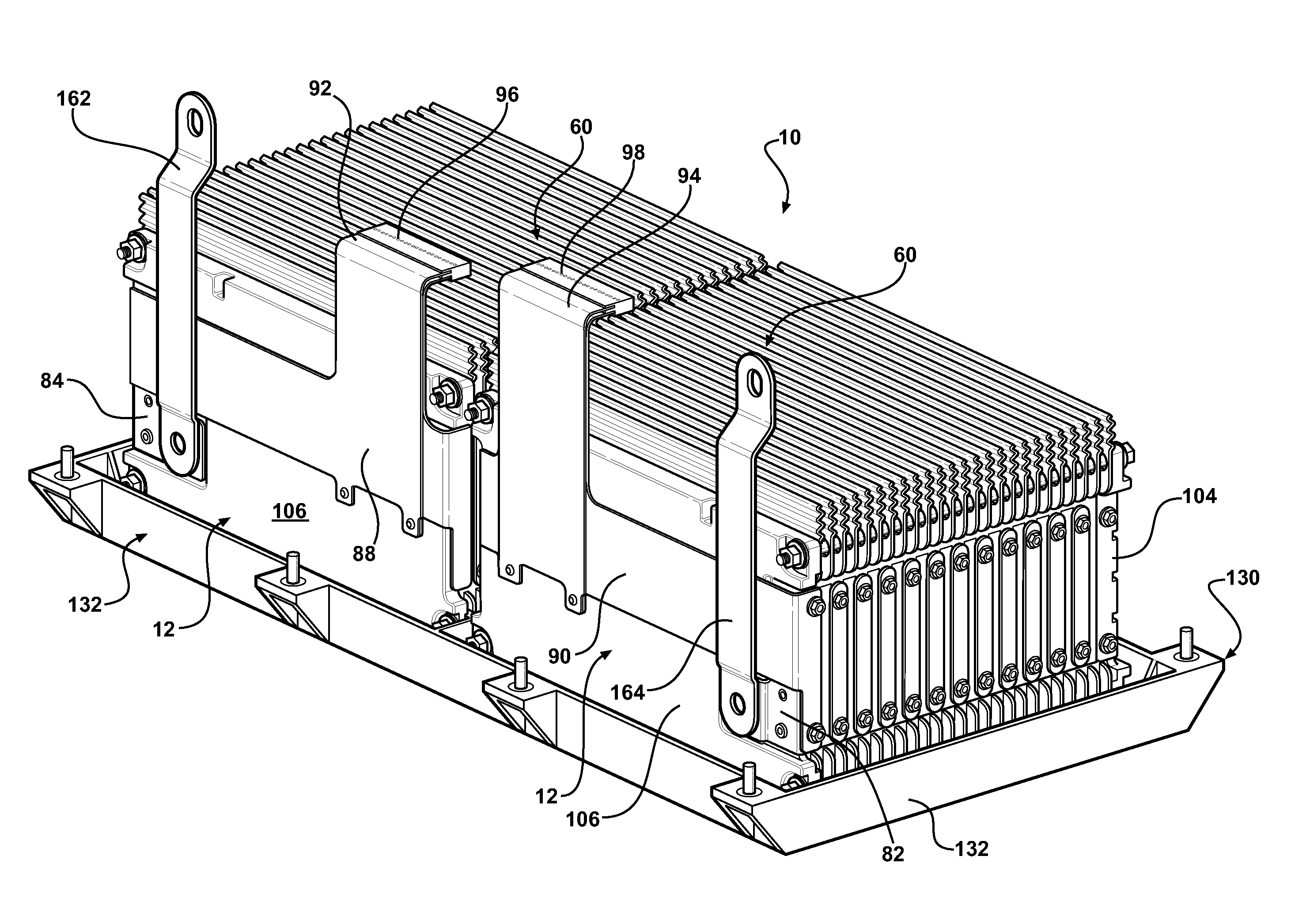
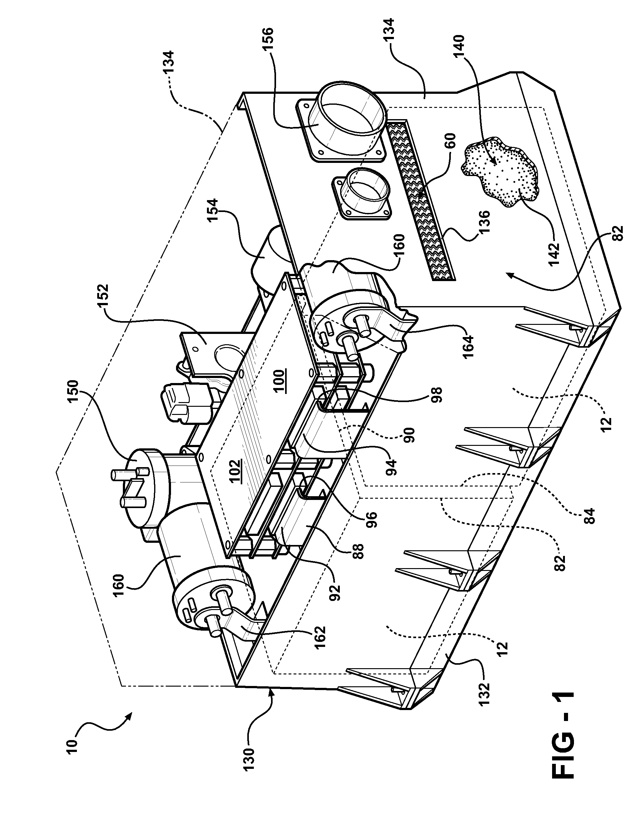
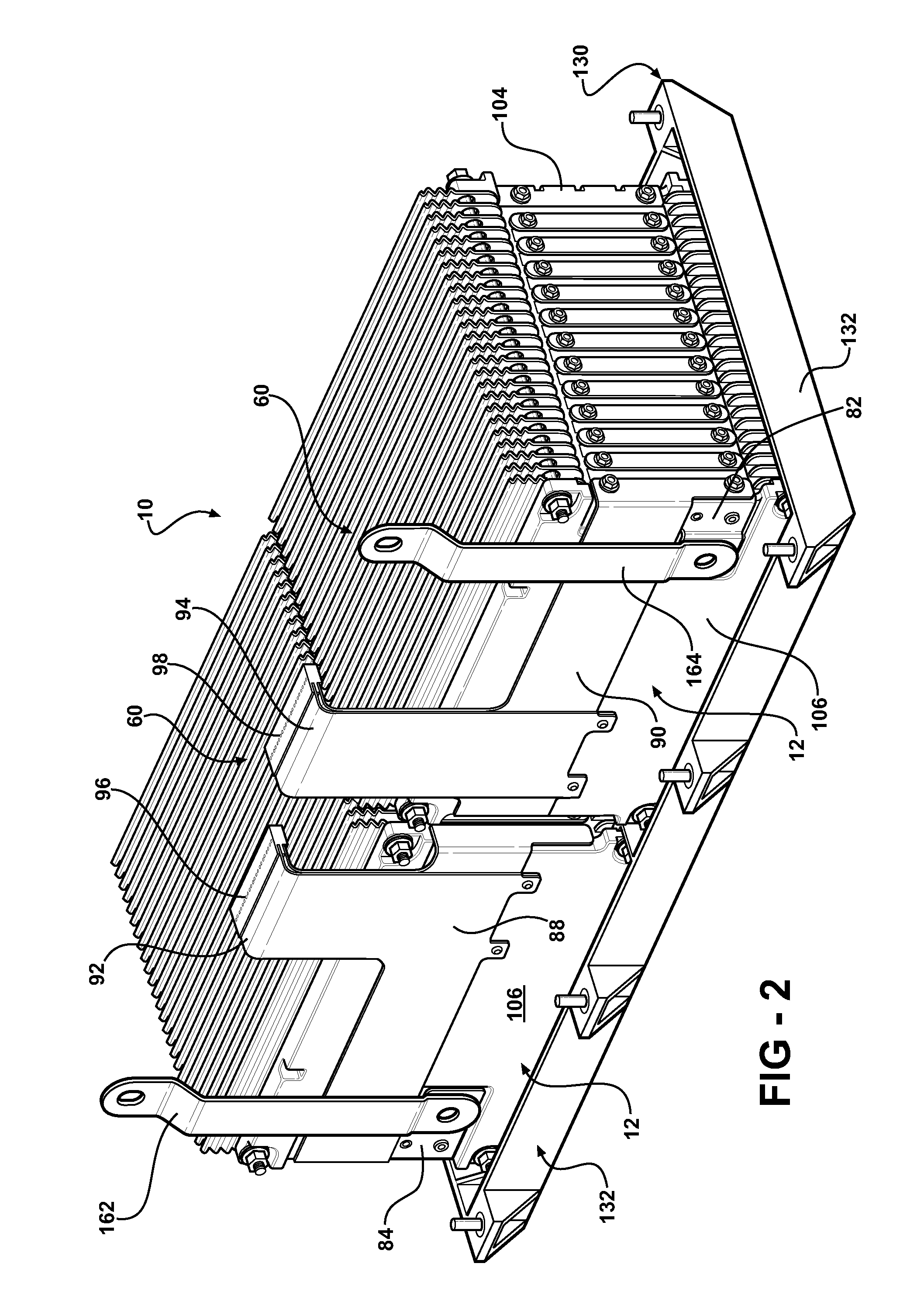
[0054]Referring to the Figures, wherein like numerals indicate like or corresponding parts, a battery unit or pack of the present invention is adaptable to be utilized in various configurations including and not limited to a horizontally or vertically stacked battery cell packaging configuration used in an automotive vehicle applications. The battery assembly or pack is generally shown at 10 in FIG. 1. The battery assembly 10 includes a plurality of battery modules, each generally shown at 12 in FIGS. 2 and 3.

[0055]Each battery module 12 includes a plurality of cells, generally indicated at 14 in FIG. 13. Preferably, each cell 14 is a lithium ion cell without limiting the scope of the present invention. Those skilled in the battery art will appreciate that other cells can be utilized with the present invention. Each cell 14 includes a plurality of battery components (not shown) co-acting between one another with electrolyte therebetween as known to those skilled in the lithium batte...


PUM

PropertyMeasurementUnit
Angleaaaaaaaaaa
Temperatureaaaaaaaaaa
Pressureaaaaaaaaaa

Abstract

A battery module of the present invention is adaptable to be utilized in various configurations including and not limited to an overlapping battery cell packaging configuration and a vertical stack battery cell packaging configuration used in an automotive vehicle. The battery module has a plurality of battery heatsink assemblies with the cells disposed therebetween. A plurality of rods extend through the each heatsink assemblies to secure the heatsink assemblies and the cell with one another to form the battery module.

Description

RELATED APPLICATIONS[0001]This non-provisional application claims priority to provisional application Ser. No. 60 / 851,684 filed on Nov. 3, 2006, and 60 / 855,787 filed on Nov. 16, 2006, and 60 / 922,632 filed on Apr. 10, 2007, and incorporated by reference herein in its entirety.FIELD OF THE INVENTION[0002]The subject invention relates to battery packs having cells and more particularly, to a battery pack for electric / hybrid vehicles having a cooling system or a heating system for cooling the cells within the battery pack.BACKGROUND OF THE INVENTION[0003]Motor vehicles, such as, for example, hybrid vehicles use multiple propulsion systems to provide motive power. This most commonly refers to gasoline-electric hybrid vehicles, which use gasoline (petrol) to power internal-combustion engines (ICEs), and electric batteries to power electric motors. These hybrid vehicles recharge their batteries by capturing kinetic energy via regenerative braking. When cruising or idling, some of the outpu...

Claims


Application Information

Patent Timeline
IPC IPC(8): H01M10/50H01M2/16H01M6/00H01M10/0525H01M10/36H01M50/211H01M50/227H01M50/242H01M50/264H01M50/291H01M50/293H01M50/503H01M50/522H01M50/569
CPCH01M2/1077Y10T29/49108H01M10/0481H01M10/0525H01M10/4207H01M10/5004H01M10/5006H01M10/5016H01M10/5032H01M10/5046H01M10/5055H01M10/5061H01M10/5083H01M10/5087Y02T10/7011H01M2/206H01M10/625H01M10/615H01M10/647H01M10/6571H01M10/6551H01M10/6555H01M10/658H01M10/656H01M10/613Y02E60/10Y02P70/50H01M50/293H01M50/522H01M50/264H01M50/291H01M50/242H01M50/227H01M50/503H01M50/569H01M50/211H01M2220/20H01M10/655H01M50/20Y02T10/70
Inventor BUCK, DERRICK SCOTTFATTIG, ROBERT N.SILK, BRUCE J.
Owner ENERDEL
Why Eureka
Try Eureka