LED lamp with heat sink optic

a technology of led lamps and optics, applied in the field of electric lamps, can solve the problems of increased lumen output, high cost, and sometimes awkward air cooling structures

Inactive Publication Date: 2009-04-02
OSRAM SYLVANIA INC
View PDF8 Cites 236 Cited by
  • Summary
  • Abstract
  • Description
  • Claims
  • Application Information

AI Technical Summary

Problems solved by technology

An essential problem is heat sinking the LED's to increase the lumen output and to preserve the potentially very long life of the LEDs.
Heavy metal heat sinks have been used along expensive and sometime awkward air cooled structures.
These are heat sinks are impractical in ordinary use and add additional cost to the lamp for material and manufacturing costs.
LED lamps are frequently being assembled by hand, which limits their reasonable market volume.

Method used


Image

  • LED lamp with heat sink optic
  • LED lamp with heat sink optic
  • LED lamp with heat sink optic

Examples


Embodiment Construction

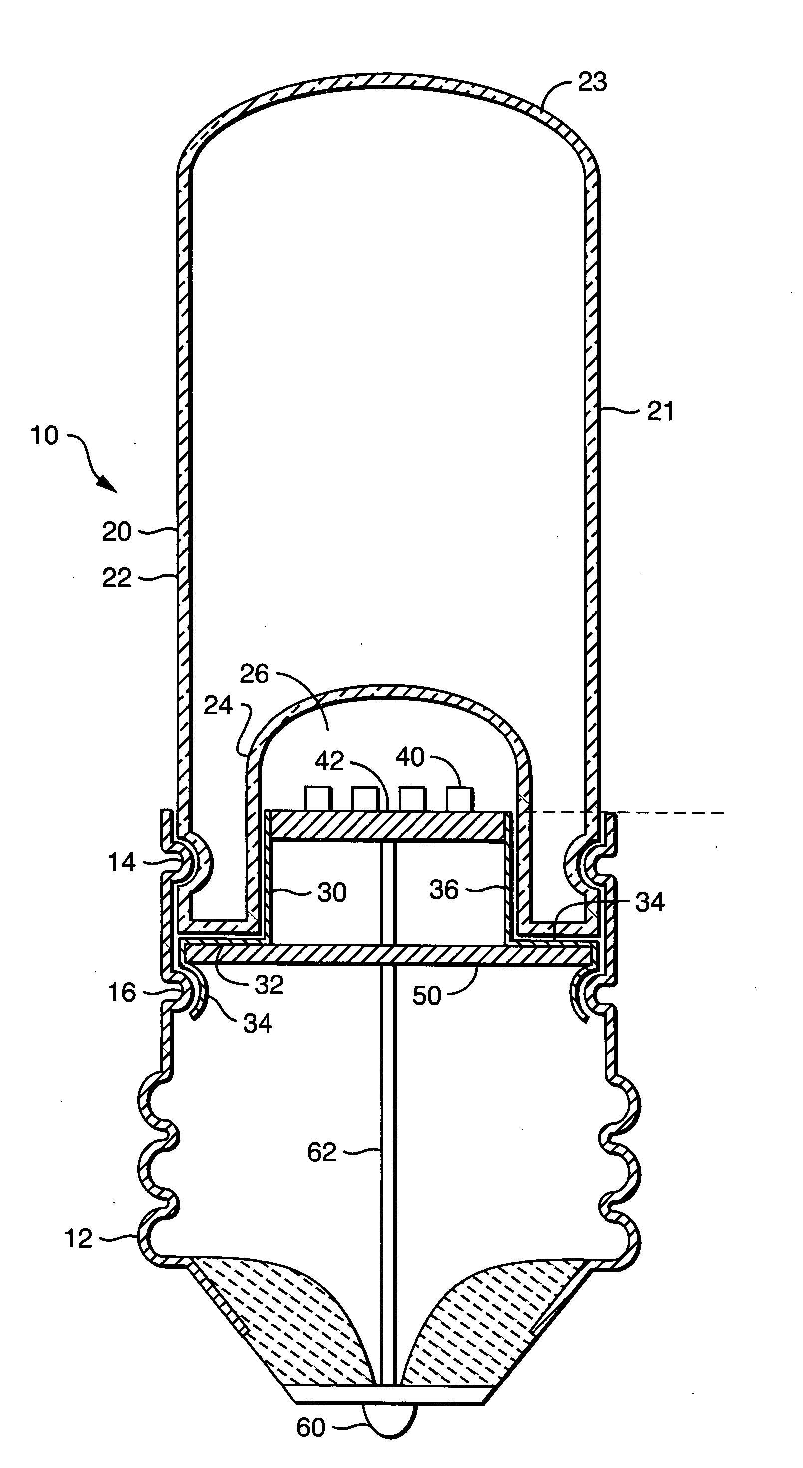
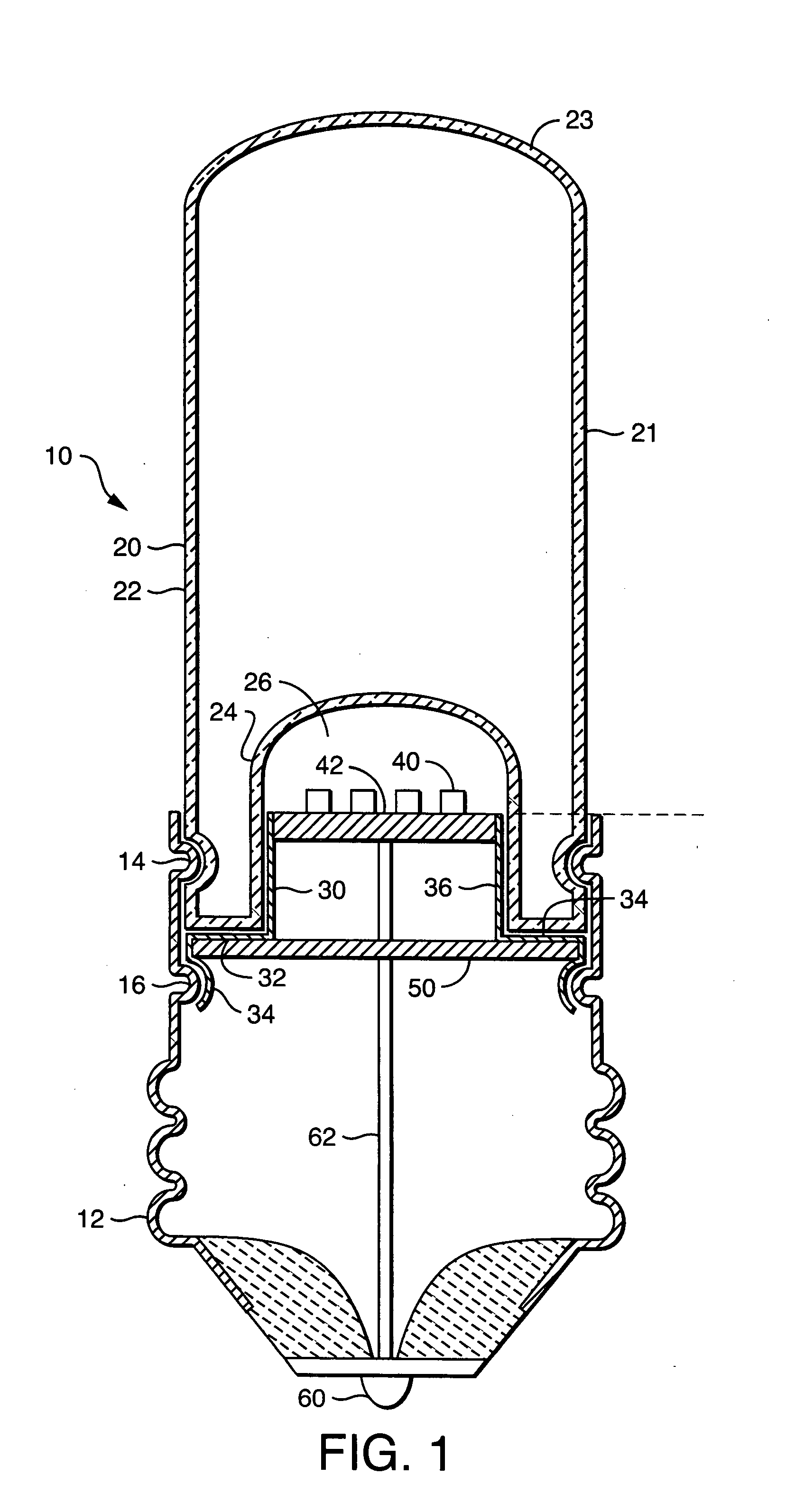
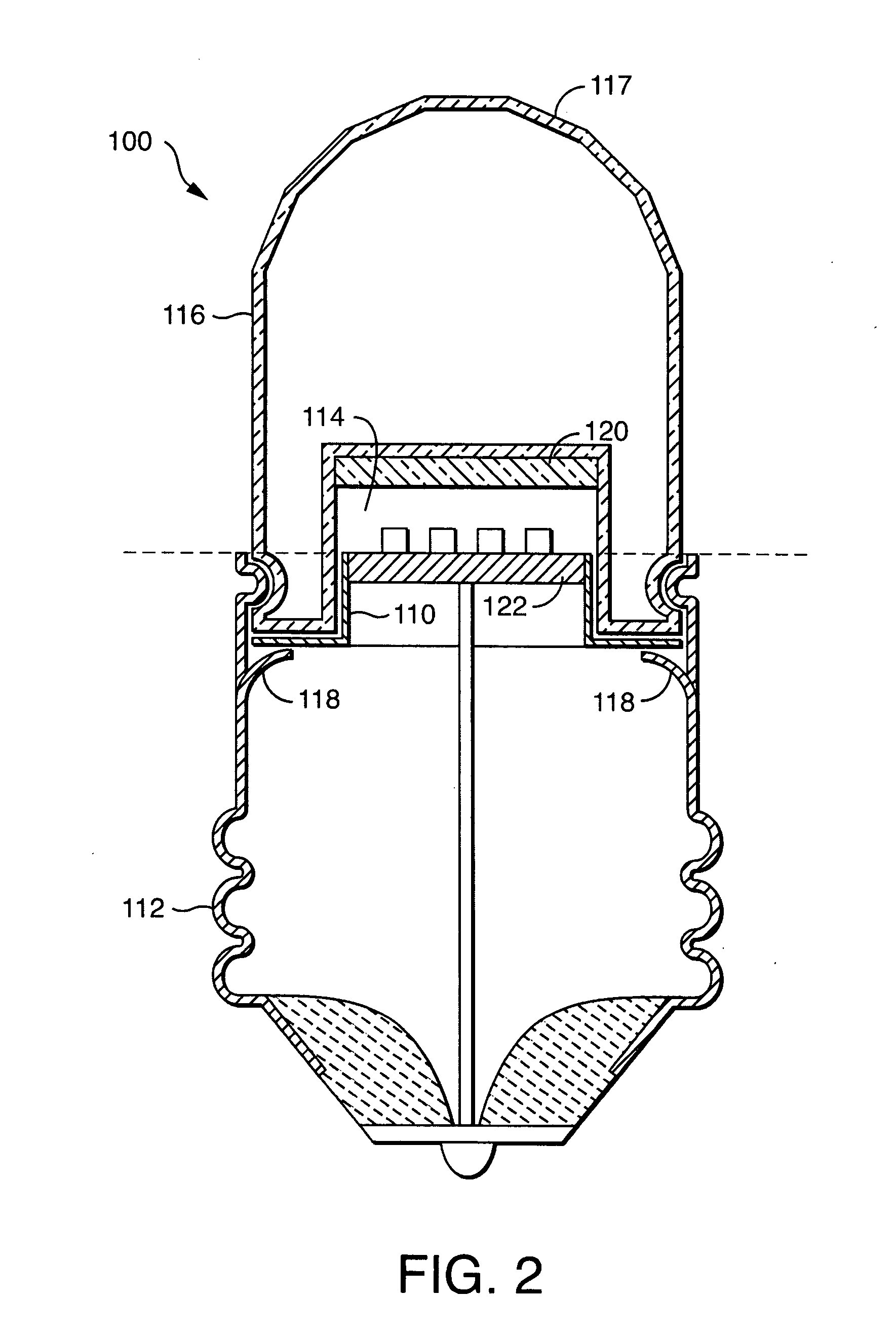
[0007]An LED lamp with a heat sink optic may be constructed from a base, an LED light source, an LED support, and a heat sinking optic.

[0008]The base may be constructed as a thread metal shell having a wall defining an interior volume. The base may be similar to those typically used in thread mounted incandescent lamp bulbs. The base includes a first electrical contact and a second electrical contact for receiving line current, and mechanical contacts for coupling to a corresponding electrical socket. In a preferred embodiment, the base includes three or more coupling points, such as indentations, defining a location plane against which the LED support ma y be positioned. A ledge, groove or step may also be formed in the base, against which an edge of the LED support may be positioned. The base may also include formed features to press against the LED support to position the LED support in tight thermal contact with the base or with heat sinking optic. The base may also be formed wi...


PUM

PropertyMeasurementUnit
temperatureaaaaaaaaaa
thermally conductiveaaaaaaaaaa
thermal conductionaaaaaaaaaa

Abstract

An LED lamp may be made with a heat sink optic. The lamp has a base having a first electrical contact and a second electrical contact for receiving current. At least one LED is mounted on a thermally conductive support; that supports electrical connections for the LED and provides thermal conduction of heat from the LED to the optic. The LED support mounted in the base and electrically coupled through the first electrical contact to electrical current. The light transmissive, and heat diffusing optic has an external an internal wall defining a cavity with the LED positioned in the cavity. The optic is in thermal contact with the LED support and mechanically coupled to the base. The snap together structure enables rapid manufacture while allowing numerous variations.

Description

TECHNICAL FIELD[0001]The invention relates to electric lamps and particularly to electric lamps with LED light sources. More particularly the invention is concerned with an electric lamp with an LED light source and a heat sinking optic.BACKGROUND ART[0002]Efficient LED lamp designed to replace the standard incandescent lamp are rapidly moving to commercial production. An essential problem is heat sinking the LED's to increase the lumen output and to preserve the potentially very long life of the LEDs. Heavy metal heat sinks have been used along expensive and sometime awkward air cooled structures. These are heat sinks are impractical in ordinary use and add additional cost to the lamp for material and manufacturing costs. LED lamps are frequently being assembled by hand, which limits their reasonable market volume.DISCLOSURE OF THE INVENTION[0003]An LED lamp may be made with a heat sink optic. The assembly includes a base having a first electrical contact and a second electrical co...

Claims


Application Information

Patent Timeline
Patent Type & Authority Applications(United States)
IPC IPC(8): F21V29/00
CPCF21V3/02F21V5/00F21V7/0008F21V17/06F21Y2101/02F21K9/135F21V29/85F21V3/0472F21V3/049F21V5/045F21V13/14F21V29/506F21K9/56F21K9/232F21K9/64F21Y2115/10F21V3/10F21V5/10F21V29/00
Inventor MEYER, WILLIAM E.
Owner OSRAM SYLVANIA INC
Why Eureka
Try Eureka