Performing rate limiting within a network

a technology of network performance and rate limitation, applied in the field of computer networking, can solve the problems of underutilized network switching capacity, network failure recovery time is not as fast, and the switching capacity of the network is underutilized,

Active Publication Date: 2010-11-18
FORTINET
View PDF36 Cites 34 Cited by
  • Summary
  • Abstract
  • Description
  • Claims
  • Application Information

AI Technical Summary

Benefits of technology

[0011]Methods and systems are described for performing rate limiting. According to one embodiment, multiple paths are provided between each pair of multi-path load balancing (MPLB) components within a Layer 2 network by establishing multiple overlapping loop-free topologies within the Layer 2 network in which each of the MPLB components is reachable by any other of the MPLB components via each of the overlapping loop-free topologies. A first MPLB component receives one or more packets associated with a flow sent by a source component, wherein the source component is sending the one or more packets associated with the flow at a particular rate. The first MPLB component forwards the one or more packets associated with the flow to a second MPLB component along a particular path in a network. A congestion metric for the particular path is determined. Based at least partially upon the congestion metric for the particular path, a determination is made regarding whether the particular path has reached a congestion threshold. In response to a determination that the particular path has reached a congestion threshold, the source component is instructed to limit the rate at which the source component is sending packets associated with the flow.

Problems solved by technology

First, because there is only one path between each pair of nodes, the network does not recover from failure as quickly as would be desired.
This takes a relatively long time, and during that time, nodes coupled via that link cannot communicate.
Another drawback is that the single path between each pair of nodes limits the cross section bandwidth of the network; thus, the switching capacity of the network is underutilized.
Furthermore, because there is only one path between each pair of nodes, it is not possible to spread and balance the traffic across a plurality of paths.
For these and other reasons, Ethernet, as it has been implemented, has not been an effective interconnect for coupling computing and storage resources in a network-based, high-performance system.

Method used


Image

  • Performing rate limiting within a network
  • Performing rate limiting within a network
  • Performing rate limiting within a network

Examples


Embodiment Construction

[0028]Methods and systems are described for performing rate limiting. One embodiment of the present invention is implemented in a loop-free switching path, reverse path learning network, such as an Ethernet network. Before describing this embodiment in detail, some additional information on Ethernet networks will be provided to facilitate a complete understanding of the invention.

Ethernet Networks

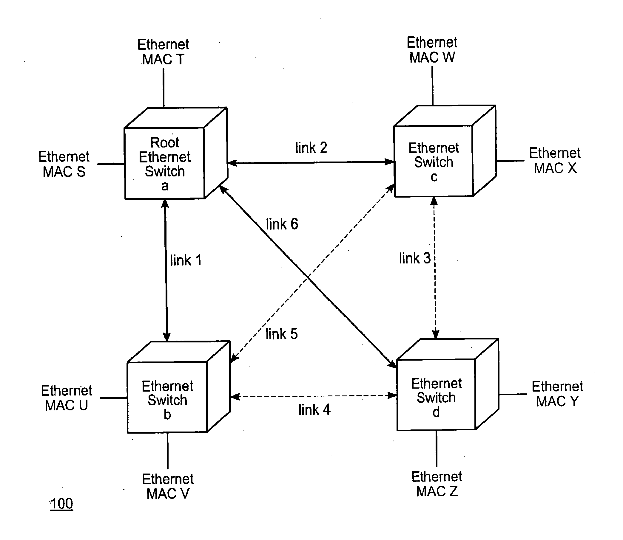
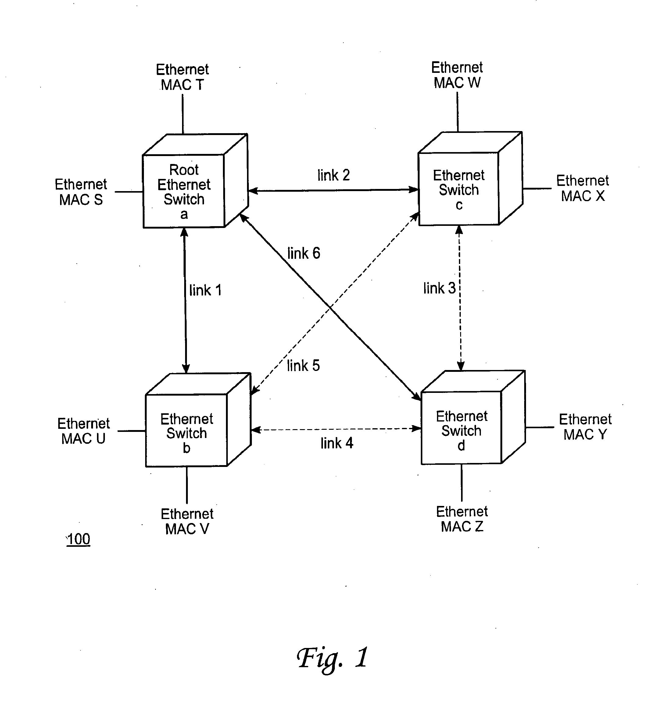
[0029]FIG. 1 shows a sample Ethernet network. As shown, the network 100 comprises four Ethernet switches a, b, c, and d. The switches are connected to each other by links 1 through 6. Coupled to each switch are two end nodes, identified by their Ethernet MAC (media access control) addresses. Specifically, switch a is coupled to the nodes with MAC addresses S and T. Switch b is coupled to the nodes with MAC addresses U and V. Switch c is coupled to the nodes with MAC addresses W and X, and switch d is coupled to the nodes with MAC addresses Y and Z.

[0030]In an Ethernet network, the path betw...


PUM


Abstract

Methods and systems for performing rate limiting are provided. According to one embodiment, multiple paths are provided between each pair of multi-path load balancing (MPLB) components within a Layer 2 network by establishing overlapping loop-free topologies in which each MPLB component is reachable by any other via each overlapping topology. A first MPLB component receives packets associated with a flow sent by a source component at a particular rate. The first MPLB component forwards the packets to a second MPLB component along a particular path in a network. A congestion metric for the particular path is determined. Based upon the congestion metric for the particular path, it is determined whether the particular path has reached a congestion threshold. In response to an affirmative determination, the source component is instructed to limit the rate at which it sends packets associated with the flow.

Description

CROSS-REFERENCE TO RELATED APPLICATIONS [0001]This is a continuation of U.S. patent application Ser. No. 11 / 732,599, filed on Apr. 3, 2007, which is a continuation-in-part of U.S. patent application Ser. No. 11 / 336,713, filed on Jan. 20, 2006, which is a continuation-in-part of U.S. patent application Ser. No. 11 / 056,436, filed on Feb. 10, 2005, which claims the benefit of priority of U.S. Provisional Application No. 60 / 545,788, filed on Feb. 18, 2004. The contents of all the aforementioned patent applications are hereby incorporated by reference in their entirety for all purposes.COPYRIGHT NOTICE[0002]Contained herein is material that is subject to copyright protection. The copyright owner has no objection to the facsimile reproduction of the patent disclosure by any person as it appears in the Patent and Trademark Office patent files or records, but otherwise reserves all rights to the copyright whatsoever. Copyright © 2004-2010, Fortinet, Inc.BACKGROUND[0003]1. Field[0004]Embodim...

Claims


Application Information

Patent Timeline
Patent Type & Authority Applications(United States)
IPC IPC(8): H04J3/14H04L45/02H04L45/121H04L45/24
CPCH04L12/4645H04L45/12H04L45/121H04L47/12H04L45/38H04L45/66H04L47/125H04L45/26H04L45/02H04L45/22H04L12/4641
Inventor TANAKA, BERT H.MALTBIE, DANIEL J.MIHELICH, JOSEPH R.
Owner FORTINET
Why Eureka
Try Eureka