
Method for improving cell load balance in cellular network and associated user equipment

Inactive Publication Date: 2010-11-18
HTC CORP
View PDF8 Cites 38 Cited by
  • Summary
  • Abstract
  • Description
  • Claims
  • Application Information

AI Technical Summary

Benefits of technology

[0010]It is therefore one objective of the present invention to provide a method for improving cell load balance in a cellular network and an associated user equipment (UE), thereby improving cell load balance in a more flexible and effective manner.
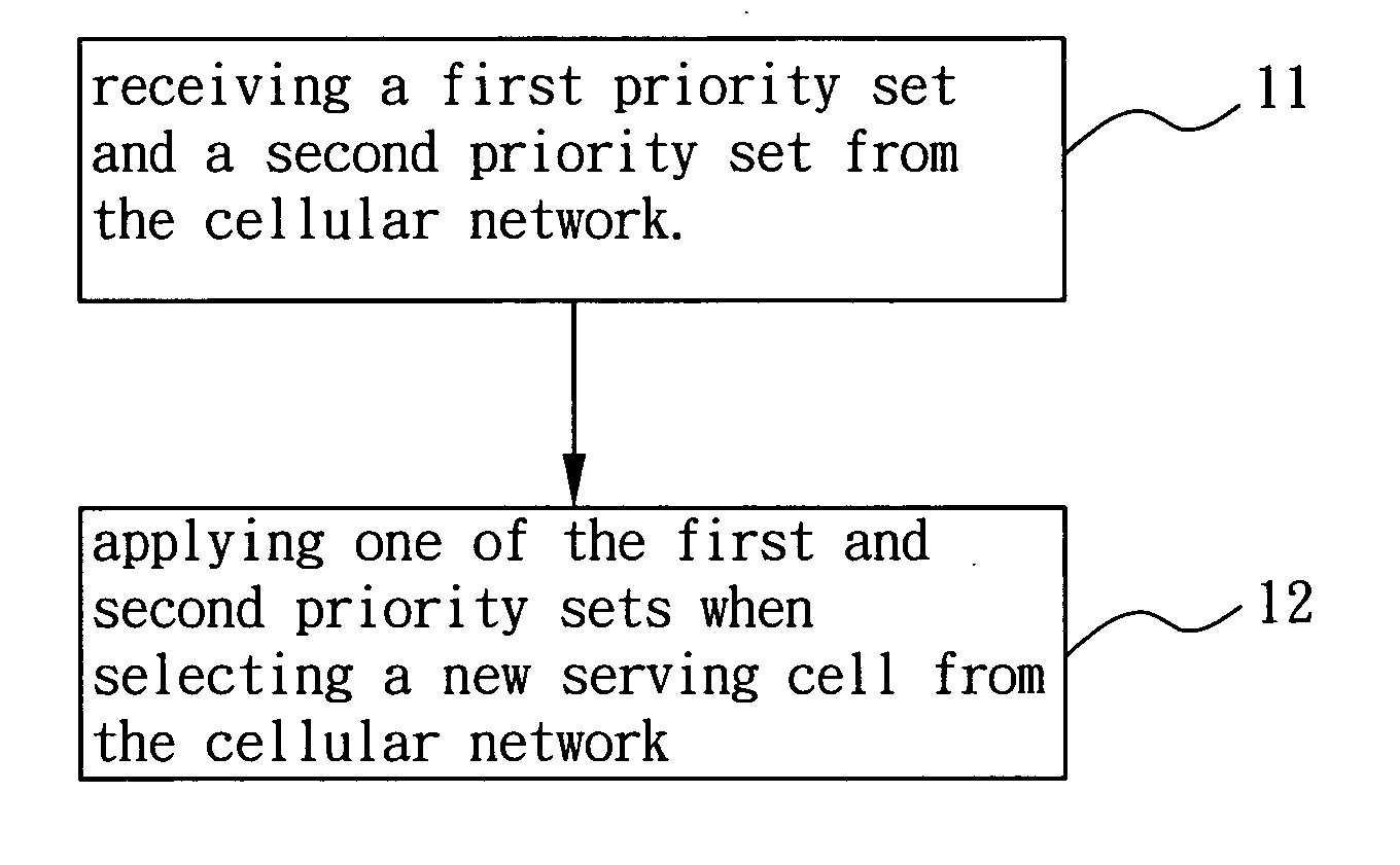
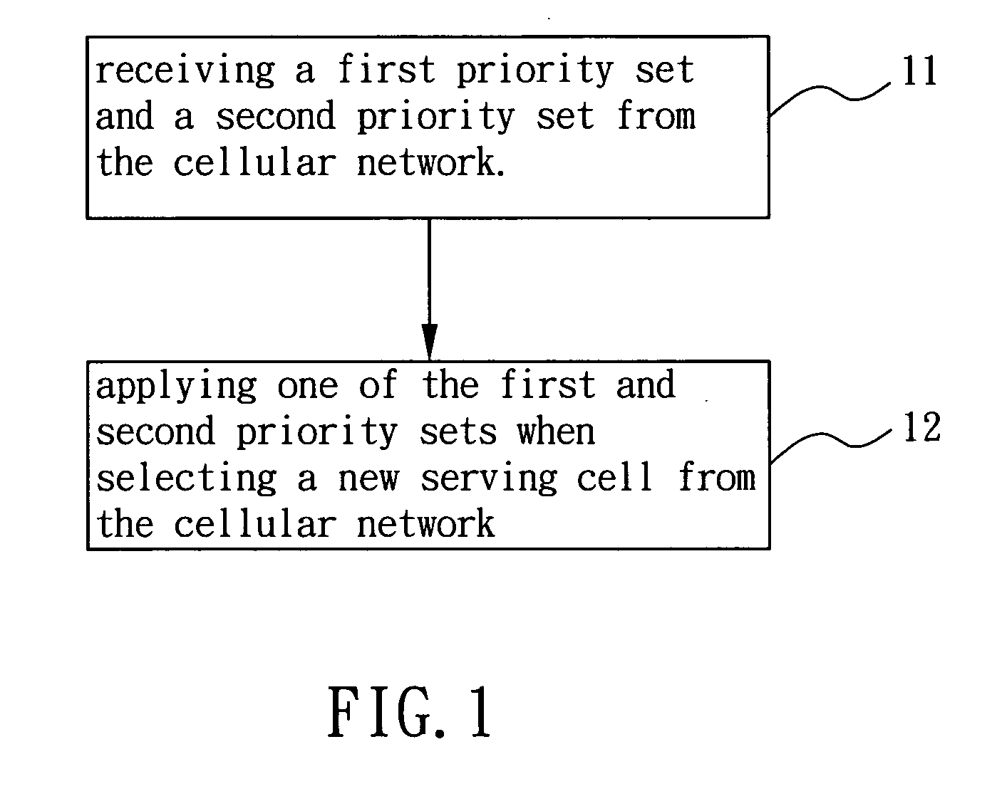
[0011]In one embodiment of the present invention, a method used in a UE for improving cell load balance in a cellular network is provided. The method comprises: receiving a first priority set and a second priority set from the cellular network, wherein each of the first and second priority sets assigns a selecting priority to at least one carrier frequency or RAT of the cellular network; and applying one of the first and second priority sets when selecting a new serving cell for the UE from the cellular network.
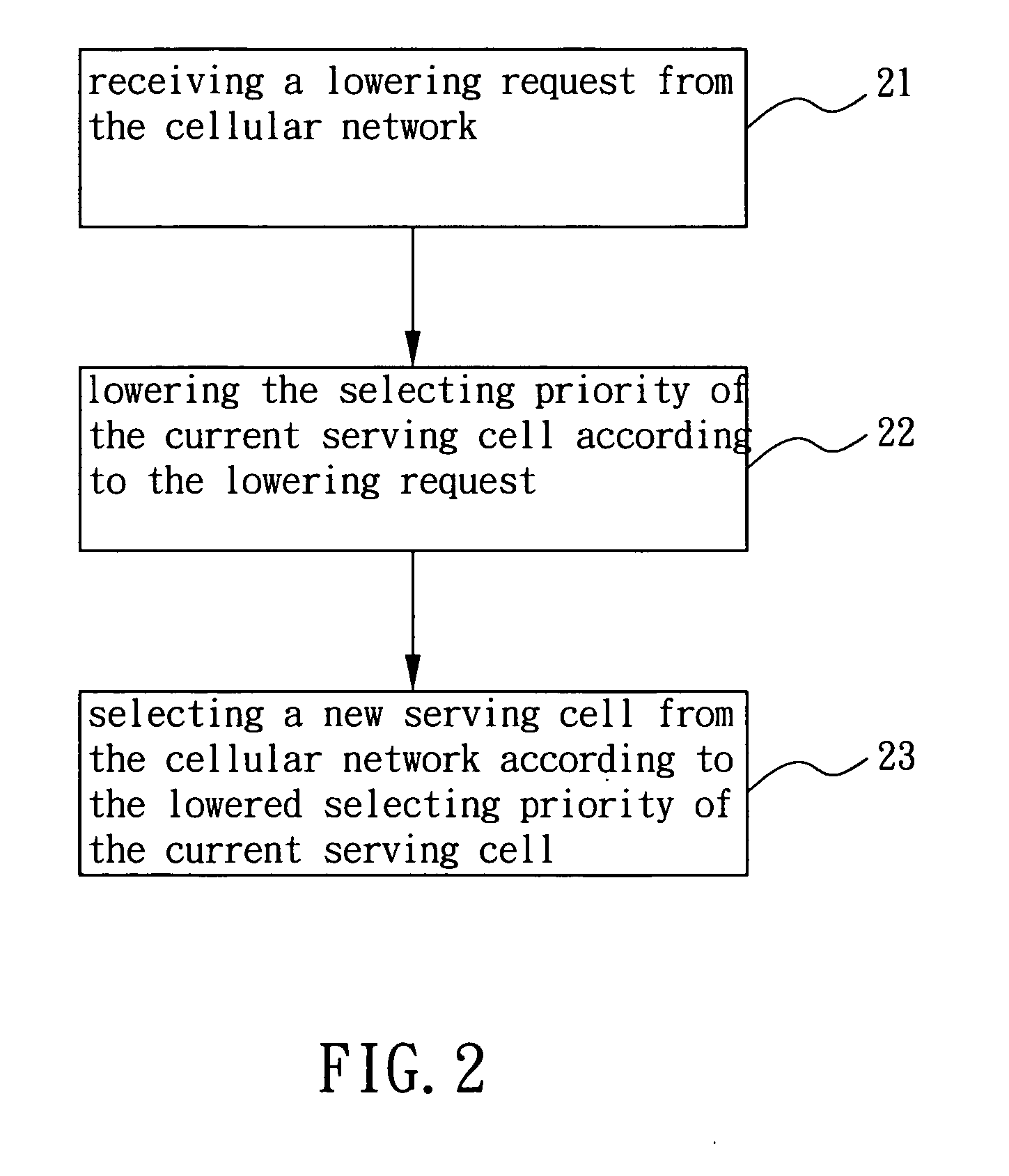
[0012]In another embodiment of the present invention, a method used in a UE for improving cell load balance in a cellular network is provided. The method comprises: receiving a lowering request from the cellular network; lowering a selecting priority of a serving cell of the UE according to the lowering request; and selecting a new serving cell for the UE from the cellular network according to the lowered selecting priority of the serving cell.

Problems solved by technology

However, there are several issues encountered in the above-mentioned approaches.
The first issue is that these approaches cannot improve cell load balance effectively.
Thus, this may cause another cell to be overloaded and fail to improve cell load balance.
Since the network can not control at what time the UE will leave the connected mode or need a handover, the approaches (2) and (3) may not direct enough UEs away to significantly reduce the load of an overloaded or heavily loaded cell in time, especially when one or more UEs want to make a connection with the network via this overloaded or heavily loaded cell.
Besides, the approach (3) is even more undesirable since it brings more signaling load on the cell to worsen the overloaded or heavily loaded situation.
However, the approach (2) can only direct the UE to a new serving cell at another carrier frequency or RAT.

Method used


Image

  • Method for improving cell load balance in cellular network and associated user equipment
  • Method for improving cell load balance in cellular network and associated user equipment
  • Method for improving cell load balance in cellular network and associated user equipment

Examples


Embodiment Construction

[0023]Reference will now to be made in detail to embodiments of the present invention, which are illustrated in the accompanying drawings. FIG. 1 is a flow chart of a method for improving cell load balance in a cellular network according to the first embodiment of the present invention. The cellular network can be, but not limited to, a UMTS network or a LTE network (e.g. LTE-Advanced network). The method is used in a user equipment (UE) of the cellular network. When the current serving cell of the UE is overloaded or heavily loaded, the method can be applied to direct the UE to select or reselect another less loaded serving cell, thereby reducing the load of the current serving cell and thus achieving more balanced cell load.

[0024]In step 11, the UE receives a first priority set and a second priority set from the cellular network. Each of the first and second priority sets assigns a selecting priority to at least one carrier frequency or radio access technology (RAT) of the cellula...


PUM


Abstract

A method for improving cell load balance in a cellular network and an associated user equipment (UE) are provided to improve cell load balance of the cellular network in a more flexible and effective manner. The method is used in the UE, and comprises receiving a first priority set and a second priority set from the cellular network and applying one of the first and second priority sets when selecting a new serving cell from the cellular network. Each of the first and second priority sets assigns a selecting priority to at least one carrier frequency or radio access frequency of the cellular network

Description

BACKGROUND OF INVENTION[0001]1. Field of the Invention[0002]The present invention relates to cellular networks, and more particularly to a method for improving cell load balance in the cellular network and an associated user equipment.[0003]2. Description of the Prior Art[0004]In a Universal Mobile Telecommunications System (UMTS) network or Long Term Evolution (LTE) network, when a cell is overloaded or heavily loaded, the network can try to alleviate the load of the cell by directing user equipments (UE) served by the cell to another less loaded cell, so as to improving cell load balance. There are several conventional approaches to direct the UE away from its current serving cell:[0005](1) The network can change a set of priorities of different carrier frequencies or Radio Access Technologies (RAT) provided in system information broadcasted to the UE. In the UMTS or LTE network, the UE in an idle mode performs cell selection and reselection to select a serving cell to camp on, an...

Claims


Application Information

Patent Timeline
IPC IPC(8): H04W72/00
CPCH04W36/22
Inventor CHEN, TE-MINGJEN, YU-CHIH
Owner HTC CORP
Learn More