
Orthopedic Plate Blocking Assembly

a technology of blocking assembly and orthopaedic plates, applied in the field of orthopaedic plates, can solve the problems of fasteners disconnecting from the plate, unique challenges in the structure of spinal elements for the use of orthopaedic plates,

Active Publication Date: 2010-11-18
GLOBUS MEDICAL INC
View PDF2 Cites 39 Cited by
  • Summary
  • Abstract
  • Description
  • Claims
  • Application Information

AI Technical Summary

Benefits of technology

[0006]In an exemplary embodiment, the present invention provides an orthopedic plate blocking assembly that can be used for the fixation or fastening of an orthopedic plate to bone tissue. In particular, the present invention, in one embodiment, provides an orthopedic plate having a plurality of cavities where each cavity is configured and dimensioned to receive a bone anchoring member. The orthopedic plate also provides a blocking mechanism having a plurality of engaged blocking members that block the bone anchoring members to prevent the bone anchoring members from “backing out” of cavities once the bone anchoring members are finally seated in the cavities.

Problems solved by technology

However, the structure of spinal elements presents unique challenges to the use of orthopedic plates for supporting or immobilizing vertebral bodies.
Among the challenges involved in supporting or fusing vertebral bodies is the effective installation of an orthopedic plate that will resist migration despite the rotational and translational forces placed upon the plate resulting from spinal loading and movement.
Furthermore, over time, it has been found that as a result of the forces placed upon the orthopedic plate and anchors resulting from the movement of the spine and / or bone deterioration, the orthopedic anchors can begin to “back out” from their installed position eventually resulting in the fasteners disconnecting from the plate.

Method used


Image

  • Orthopedic Plate Blocking Assembly
  • Orthopedic Plate Blocking Assembly
  • Orthopedic Plate Blocking Assembly

Examples


Embodiment Construction

[0014]The following description of the preferred embodiment(s) is merely exemplary in nature and is in no way intended to limit the invention, its application, or uses.

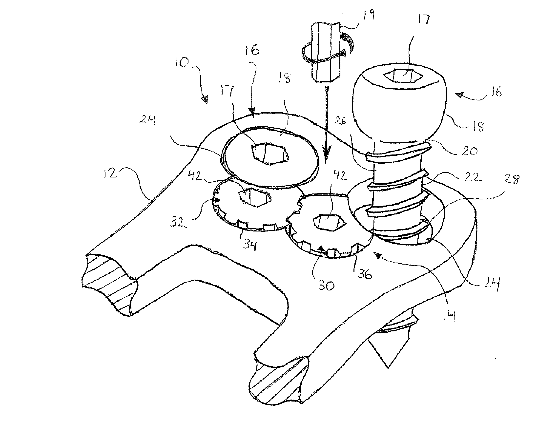
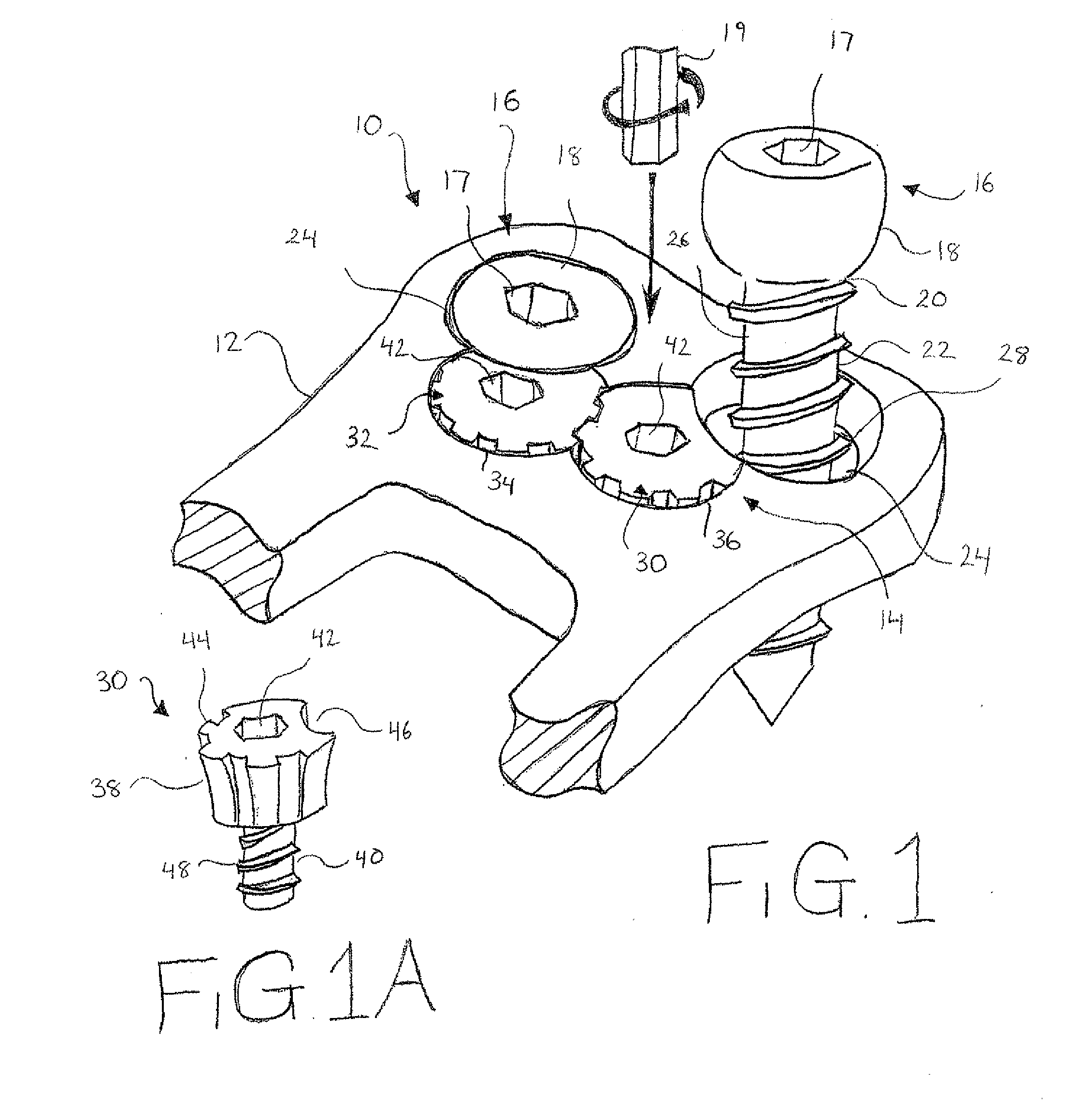
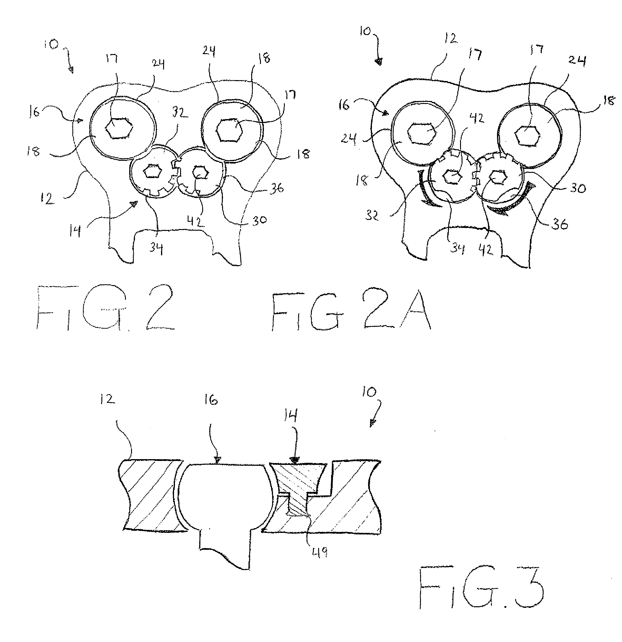
[0015]With reference to FIG. 1 an embodiment of an orthopedic plate blocking assembly 10 is illustrated. Although not shown in the environment of use, the orthopedic plate blocking assembly 10 is adapted to be used for supporting and / or immobilizing adjacent bones or bone segments, such as vertebrae, in the spine. The blocking assembly 10 preferably includes an orthopedic plate 12, a blocking mechanism 14, and at least one bone screw 16. Even though only the bone screw 16 is identified as the fastening or anchoring element, it is contemplated that the fastening or anchoring element can be any of the following, including, but not limited to, a hook, a pin, or a nail. Further, although only two bone screws 16 are shown in FIG. 1, it is contemplated that the number of screws 16 will correlate to the size of the plate 12....


PUM


Abstract

In an exemplary embodiment, the present invention provides an orthopedic plate blocking assembly that can be used for the fixation or fastening of an orthopedic plate to bone tissue. In particular, the present invention, in one embodiment, provides an orthopedic plate having a plurality of cavities where each cavity is configured and dimensioned to receive a bone anchoring member. The orthopedic plate further provides a blocking mechanism having a plurality of blocking members that block the bone anchoring members to prevent the bone anchoring members from “backing out” of cavities once the bone anchoring members are finally seated in the cavities.

Description

FIELD OF THE INVENTION[0001]The present invention is directed to orthopedic plates and, in particular, to a blocking assembly for securing an orthopedic plate to bone tissue.BACKGROUND OF THE INVENTION[0002]The use of orthopedic plates for correction of spinal deformities and for fusion of vertebrae is well known. Typically, a rigid plate is positioned to span bones or bone segments that need to be supported or immobilized with respect to one another. The orthopedic plate is fastened to the bone tissue with bone anchors or screws so that the plate remains in contact with and supports the bone or bone segments.[0003]However, the structure of spinal elements presents unique challenges to the use of orthopedic plates for supporting or immobilizing vertebral bodies. Among the challenges involved in supporting or fusing vertebral bodies is the effective installation of an orthopedic plate that will resist migration despite the rotational and translational forces placed upon the plate res...

Claims


Application Information

Patent Timeline
Patent Type & Authority Applications(United States)
IPC IPC(8): A61B17/80
CPCA61B17/8033A61B17/7059
Inventor SUH, SEAN
Owner GLOBUS MEDICAL INC
Learn More