Impacted orthopedic bone support implant

a bone support implant and implant technology, applied in the field of orthopedic mesh implants, can solve the problems of limiting the advantages that may be realized, the cost of manufacturing and availability of such implants, etc., and achieve the effect of facilitating the reconstruction and/or repair of bone structures

Inactive Publication Date: 2009-05-26
SDGI HLDG
View PDF21 Cites 130 Cited by
  • Summary
  • Abstract
  • Description
  • Claims
  • Application Information

AI Technical Summary

Benefits of technology

[0008]According to one form of the invention, there is provided an implant for insertion into bone structures. The implant comprises a hollow body having an interior chamber, a first and second end for bearing against bone tissue and each end having an opening providing communication with the interior chamber. The hollow body is formed to include one or more mesh sides having a grid work of openings into the interior chamber. Thus, the invention provides a device that is implantable into bone structures and provides a depot for deposition of bone growth inducing material to promote bone growth and to provide support for weak bone structures.

Problems solved by technology

While implants are known that may provide stability between adjacent bony structures, the effectiveness, as well as the cost of manufacture and availability of such implants, limits the advantages that may be realized.

Method used


Image

  • Impacted orthopedic bone support implant
  • Impacted orthopedic bone support implant
  • Impacted orthopedic bone support implant

Examples


Embodiment Construction

[0027]For the purposes of promoting an understanding of the principles of the invention, reference will now be made to the embodiments illustrated herein and specific language will be used to describe the same. It will nevertheless be understood that no limitation of the scope of the invention is thereby intended. Any alterations and further modifications in the described processes, systems or devices, and any further applications of the principles of the invention as described herein, are contemplated as would normally occur to one skilled in the art to which the invention relates.

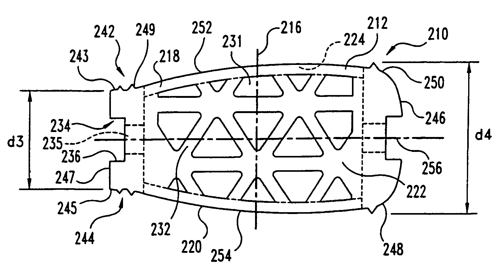
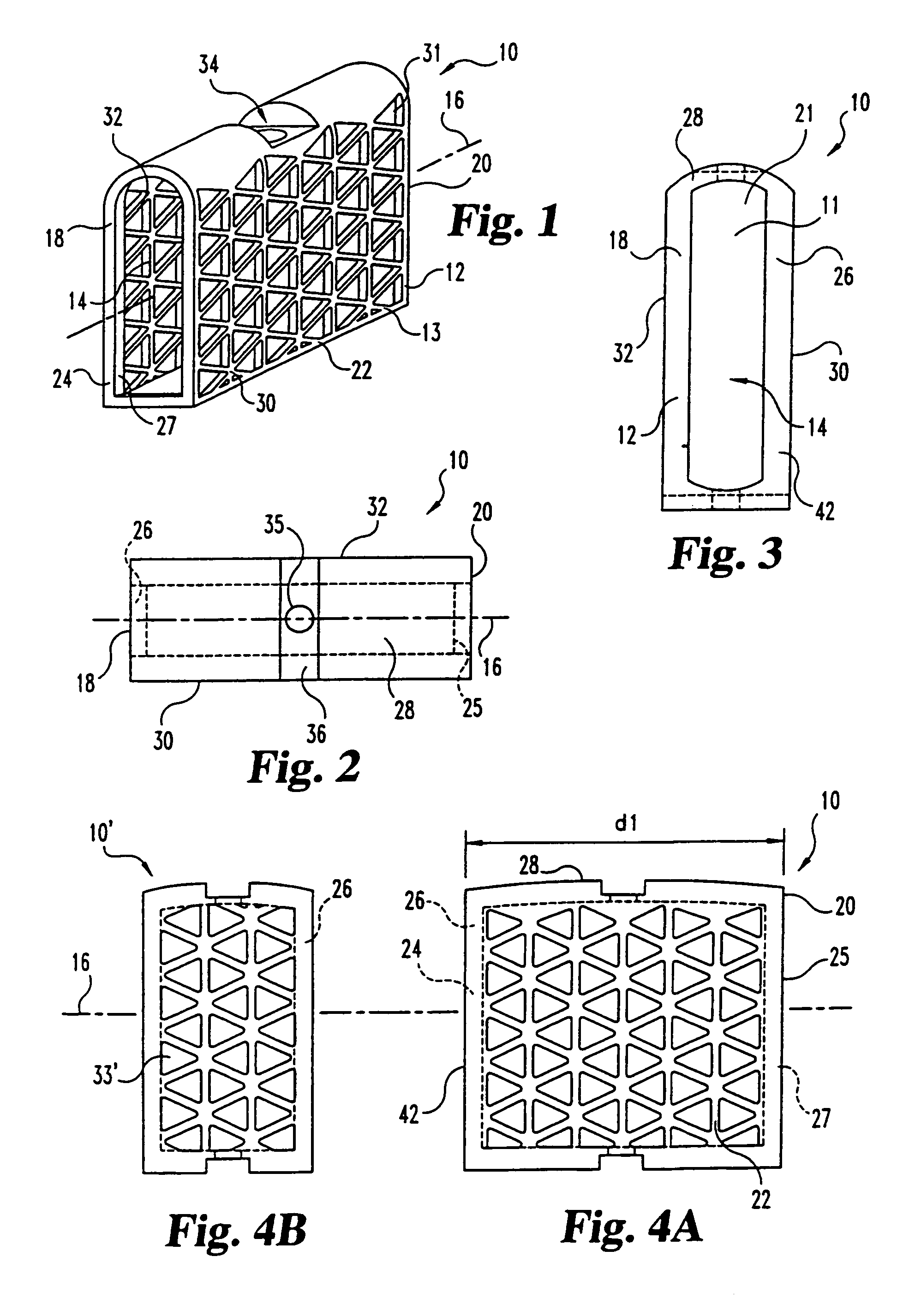
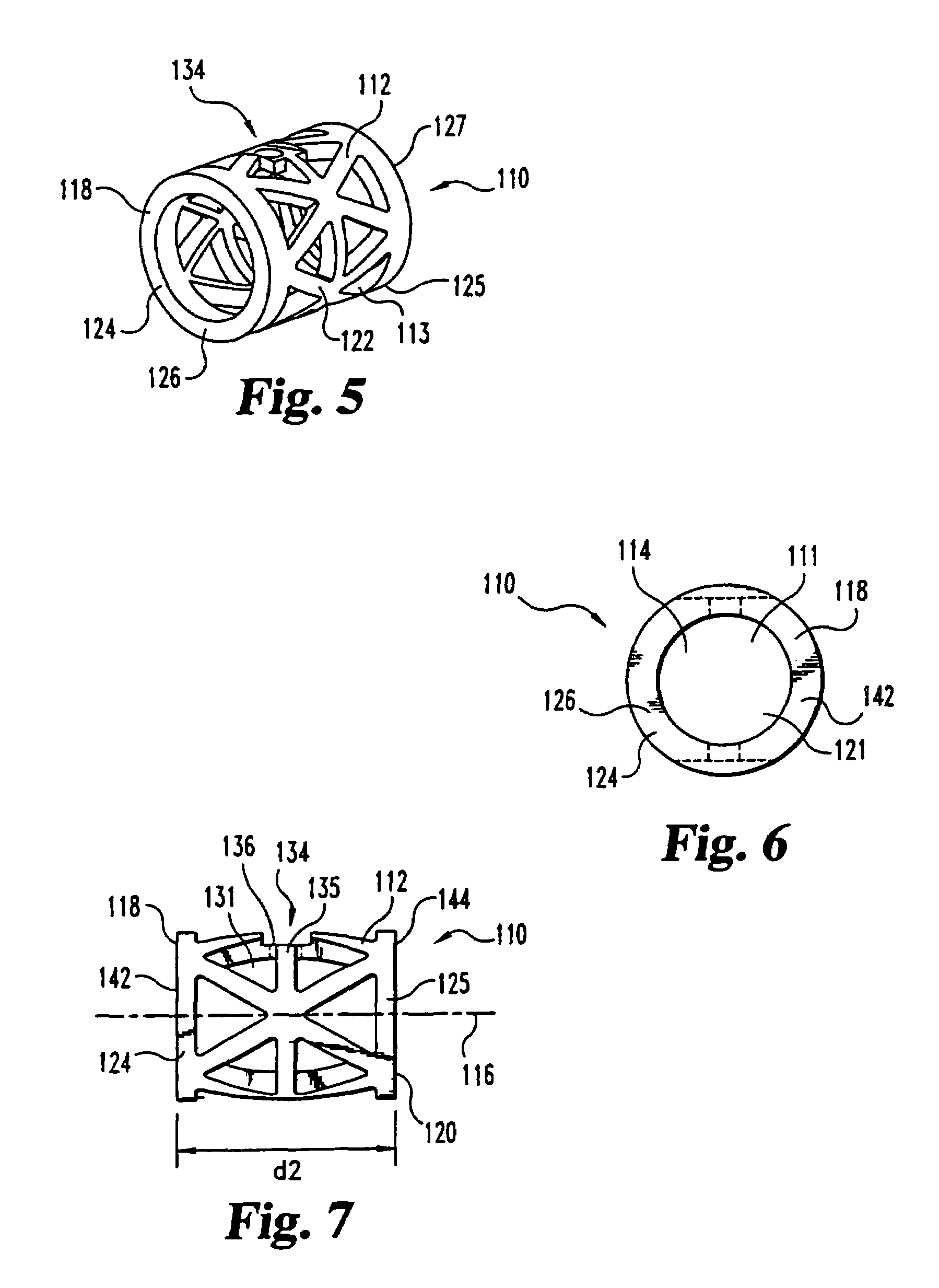
[0028]The present invention contemplates an implant for insertion into bone structures. In one aspect of the invention, the implant provides a device for supporting weak bone structures. In other aspects, the implant provides a receptacle for deposition of bone growth material. In still other aspects the implant of this invention is intended to replace current mesh or cage-type devices for engagement with...


PUM


Abstract

This invention relates to a porous bone implant (10, 110, and 210), a method of manufacturing the implant and a method of orthopedic treatment. The mesh implant can be manufactured using extrusion techniques and a variety of cutting and machining processes to provide the implant with the desired structural features and in the required dimensions to be matingly received within the bone defect or cavity. The implant can be used to strengthen bone structures and support bone tissue adjacent to a defect of cavity. Thus, the implant can be used to provide improved treatment of patients having bone defects or diseases with decreased postoperative pain and a shorter recovery time.

Description

CROSS-REFERENCE TO RELATED APPLICATION[0001]The present application claims the benefit of U.S. Provisional Application Ser. No. 60 / 160,506 filed on Oct. 20, 1999, and entitled “Impacted Orthopedic Bone Implant,” which is hereby incorporated by reference in its entirety.BACKGROUND OF THE INVENTION[0002]The present invention concerns a device for implantation into bone tissues, a method of manufacturing such a device, and a method of orthopedic treatment. More specifically, this invention is directed to an orthopedic mesh implant for implantation into bone cavities to support bone tissue adjacent to the cavity. The invention is also specifically directed to methods of manufacturing a mesh implant and to methods for treating patients using the mesh implant.[0003]The repair and reconstruction of bone structures having a defect, such as a cavity, crack or chip, can be accomplished by directly fixing bone structures adjacent a defect to each other, such as by plate(s) and screw(s). In oth...

Claims


Application Information

Patent Timeline
Patent Type & Authority Patents(United States)
IPC IPC(8): A61F2/44A61B17/14A61B17/16A61F2/00A61F2/28A61F2/30A61F2/46
CPCA61F2/2846A61F2/4455A61F2/446A61F2/4603A61B17/14A61B17/1604A61F2/28A61F2/30965A61F2/442A61F2/4611A61F2002/2835A61F2002/2839A61F2002/30112A61F2002/30138A61F2002/30153A61F2002/30154A61F2002/30156A61F2002/30235A61F2002/30271A61F2002/30324A61F2002/30593A61F2002/30616A61F2002/30774A61F2002/30777A61F2002/30785A61F2002/30787A61F2002/30789A61F2002/3082A61F2002/30836A61F2002/30879A61F2002/30912A61F2002/3097A61F2002/4475A61F2002/4623A61F2002/4649A61F2002/4681A61F2230/0004A61F2230/0017A61F2230/0019A61F2230/0021A61F2230/0023A61F2230/0069A61F2230/0082A61F2250/0036A61F2310/00017A61F2310/00023A61F2310/00179A61F2002/30261
Inventor BRANCH, CHARLES L.WHITE, JOHN L.ESTES, BRADLEY T.RAY, III, EDDIE
Owner SDGI HLDG
Why Eureka
Try Eureka