Bone implants with central chambers

a bone implant and central chamber technology, applied in the field of implants with central chambers, can solve the problems of limiting the efficacy of implants, not always possible or even desirable to use autografts, and additional patient discomfort during rehabilitation, and achieve the effect of facilitating the implantation of spacers

Inactive Publication Date: 2006-08-08
SYNTHES USA
View PDF109 Cites 138 Cited by
  • Summary
  • Abstract
  • Description
  • Claims
  • Application Information

AI Technical Summary

Benefits of technology

[0046]The present invention also relates to a discrete spacer used in conjunction with any of the other embodiments of the implant. The spacer comprises a piece of allogenic bone conforming in size and shape with a portion of an end plates of the vertebrae and has a wedge-shaped profile with substantially smooth top and bottom surfaces. The intersecting regions between

Problems solved by technology

This is primarily due to the limited applicability of xenografts, transplants from another species.
It is not always possible or even desirable to use an autograft.
Furthermore, the removal of material, oftentimes involving the use of healthy material from the pelvic area or ribs, has the tendency to result in additional patient discomfort during rehabilitation, particularly at the location of the material removal.
Grafts formed from synthetic material have also been developed, but the difficulty in mimicking the properties of bone limits the efficacy of these implants.
Sections of bones with regions having narrow cross-sections, as seen for example with thicknesses X1 and X3, may be rejected for use in certain applications because the wall thickness does not have sufficient strength.
Thus, in the case that a bone section is found to have a region with a wall thickness less than a minimum acceptable thickness, such a bone section is rejected as being unsuitable for use in a bulk configuration.
The minimum thickness standards imposed on the use of bone sections results in the rejection of substantial quantities of bone sections, and thus an inefficient use of the material.
Additionally, the strain to failure of cancellous bone is about 5–7%, while cortical bone can only withstand 1–3% strain before failure.
It should also be noted that these mechanical characteristics may degrade as a result of numerous factors such as any chemical treatment applied to the bone material, and the manner of storage after removal but prior to implantation (i.e. drying of the bone).
Notably, however, are many differences from wood such as the abrasive nature of hydroxyapatite and the poor response to local heating during machining of a bone.
Furthermore, while wood is readily available in considerable quantity, bone material is an extremely limited resource that must be used in an extremely efficient manner.
While an allograft of a particular shape may be formed using this process, the process is limited to forming an allograft by compressing cancellous bone chips.
Thus, numerous molds are required in order to produce allografts of different sizes, and the use of bulk-size allograft source material is not facilitated.
With a rapidly increasing demand in the medical profession for devices incorporating bone material, the tremendous need for the tissue material itself, particularly allograft tissue material, presents a considerable challenge to the industry that supplies the material.
For example, the size of cortical bone fragments ne

Method used


Image

  • Bone implants with central chambers
  • Bone implants with central chambers
  • Bone implants with central chambers

Examples


first embodiment

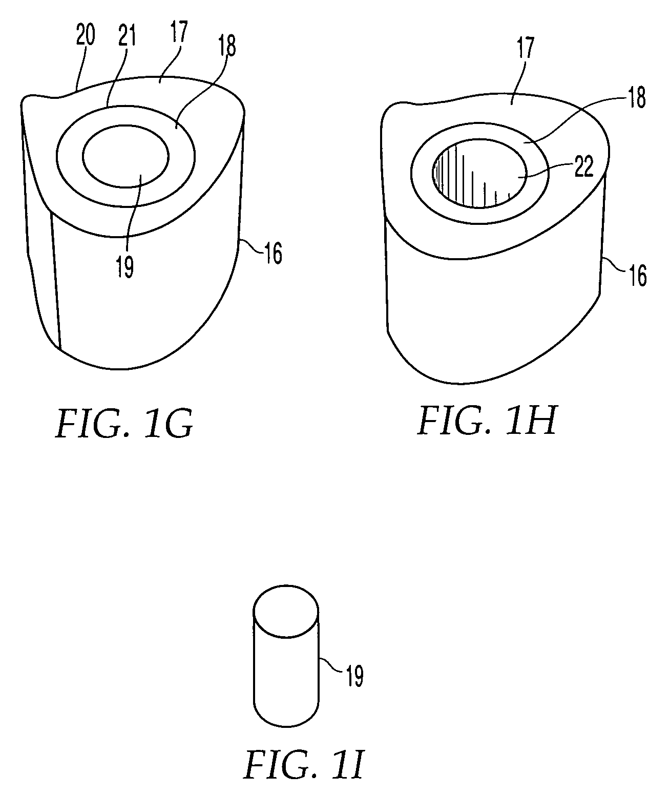
[0107]FIG. 1G shows implant 16 having an outer sheath 17, an intermediary sheath 18, and a core 19. It should be noted that while bone sections described herein are referred to as sleeves, these components need not be cylindrical or otherwise symmetrical. In this embodiment, outer sheath 17 is a bone section, for example of a femur, that has the outer surface or contour naturally found on a femur. Thus, the outer surface 20 of outer sheath 17 does not require machining and is not machined. The inner surface 21 of outer sheath 17 has been machined to a particular configuration so that intermediary sheath 18 fits within outer sheath 17. Alternatively, as shown in FIG. 1H, implant 16 may have a through hole 22 instead of a core 19, creating a cavity in implant 16. If a through-hole is provided instead of core 19, a hollow implant may be created and bone growth materials such as bone materials in the form of chips, slurries, or fibers, as well as bone inducing substances can be provided...

second embodiment

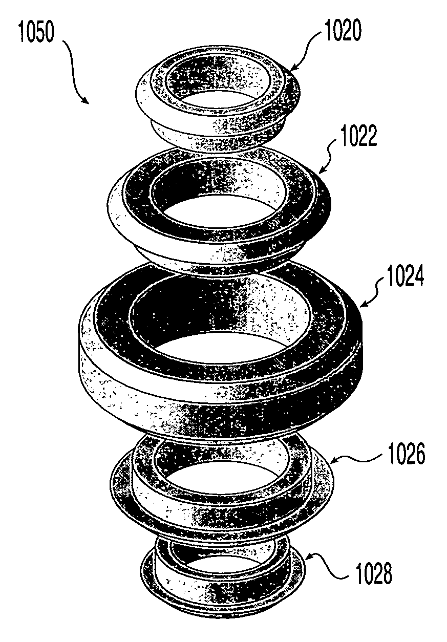
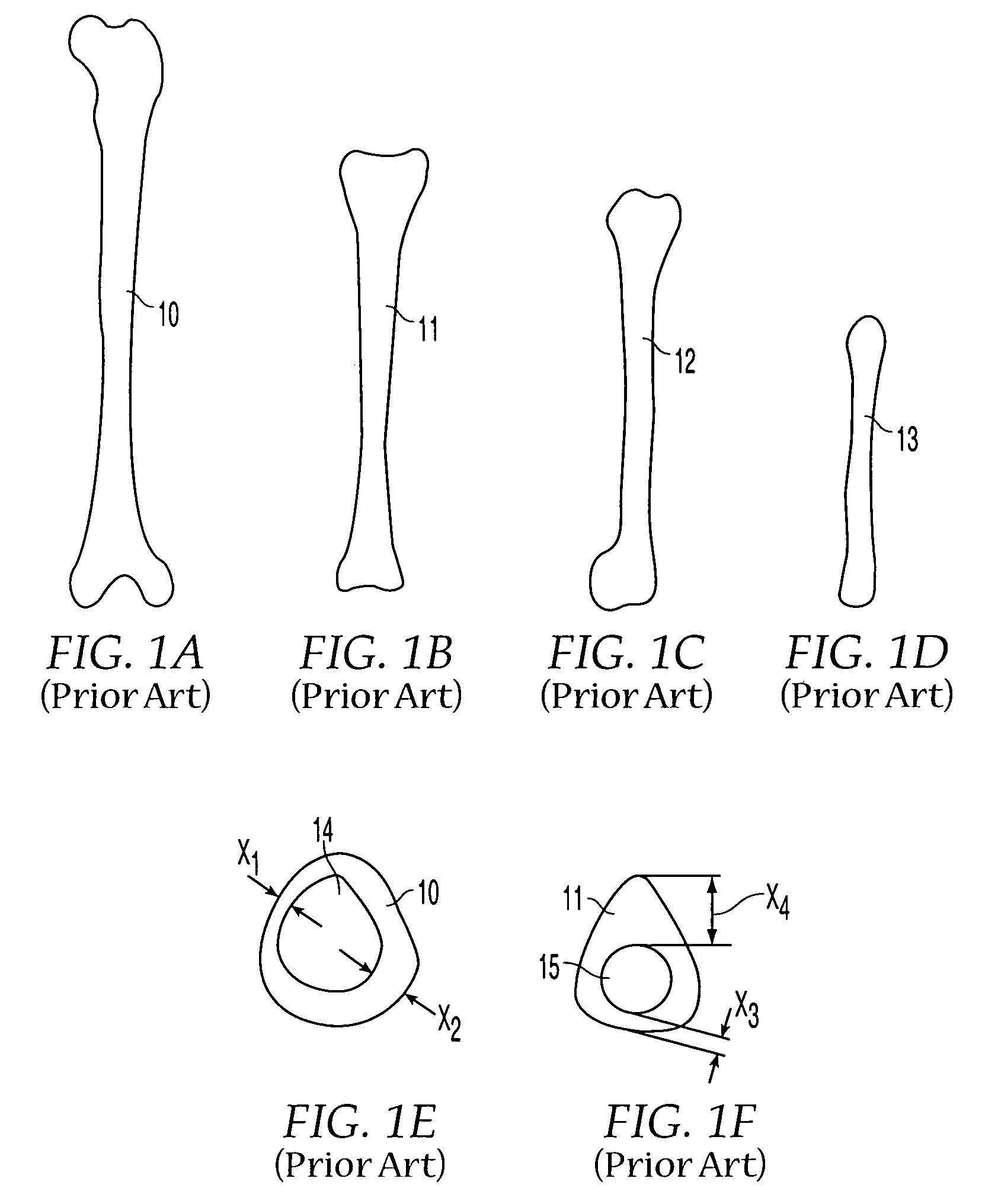
[0109]As shown in FIG. 1J, in the present invention many types of bones may be combined in layers to form bone stock 25′. A radius 13 may be encased in humerus sleeve 12, which may be encased in tibia sleeve 11, which may further be encased in femur sleeve 10 that retains the original outer shape of the femur. In alternate embodiments, other bones may be used, such as a fibula or ulna. By machining the inner and / or outer surfaces of each bone section, the bone sections may be inserted into each other with an interfitting relationship. This may result in a strong press-fit, but additional or alternate means of fixation may be employed, such as mechanical means.

[0110]The moisture content of the bone sections also may be varied to advantageously permit improved interlocking. Bone sections initially may be provided with moisture content as follows: (1) bone in the natural state fresh out of the donor without freezing, (2) bone in the frozen state, typically at −40° C., with moisture con...


PUM

PropertyMeasurementUnit
Pressureaaaaaaaaaa
Shapeaaaaaaaaaa

Abstract

A bone fusion implant for repair or replacement of bone includes a hollow body formed from at least two bone fragments which are configured and dimensioned for mutual engagement and which are coupled together. The hollow body may be formed of autograft, allograft, or xenograft bone tissue, and may include a core formed of at least one of bone material and bone inducing substances, with the core being disposed in the hollow body.

Description

CROSS-REFERENCE TO RELATED APPLICATIONS[0001]This is a continuation-in-part of U.S. patent application Ser. No. 09 / 363,844, filed Jul. 30, 1999, now U.S. Pat. No. 6,258,125, which claims the benefit under 35 U.S.C. § 119(e) of Provisional Application No. 60 / 095,209, filed Aug. 3, 1998; this application further claims the benefit under 35 U.S.C. § 119(e) of Provisional Application No. 60 / 191,099, filed Mar. 22, 2000.FIELD OF THE INVENTION[0002]The invention relates to an implant for orthopedic applications. More particularly, the invention is related to an implant formed from two or more bone portions. In addition, the invention relates to allogenic intervertebral implants.BACKGROUND OF THE INVENTION[0003]Bone grafts have become an important and accepted means for treating bone fractures and defects. In the United States alone, approximately half a million bone grafting procedures are performed annually, directed to a diverse array of medical interventions for complications such as f...

Claims


Application Information

Patent Timeline
IPC IPC(8): A61F2/44A61B17/88A61F2/00A61F2/02A61F2/28A61F2/30A61F2/46B29C33/26B29C43/00
CPCA61F2/28A61F2/30744A61F2/30942A61F2/44A61F2/4455A61F2/4465A61F2/4644B29C43/006A61F2/30724A61F2/3094A61F2/30965A61F2/442A61F2/4611A61F2002/2817A61F2002/2825A61F2002/2835A61F2002/2839A61F2002/30011A61F2002/30057A61F2002/30062A61F2002/30075A61F2002/30112A61F2002/30115A61F2002/30126A61F2002/30131A61F2002/30133A61F2002/30138A61F2002/30148A61F2002/30151A61F2002/30153A61F2002/30154A61F2002/30158A61F2002/30166A61F2002/30168A61F2002/30179A61F2002/302A61F2002/3021A61F2002/30212A61F2002/30224A61F2002/30225A61F2002/30228A61F2002/3023A61F2002/30232A61F2002/30233A61F2002/30235A61F2002/30237A61F2002/30238A61F2002/3024A61F2002/30261A61F2002/3028A61F2002/30299A61F2002/30322A61F2002/30324A61F2002/30327A61F2002/30329A61F2002/30331A61F2002/30332A61F2002/30354A61F2002/30367A61F2002/30377A61F2002/3038A61F2002/30382A61F2002/30383A61F2002/30387A61F2002/30405A61F2002/30411A61F2002/30426A61F2002/30433A61F2002/30434A61F2002/30436A61F2002/30441A61F2002/30443A61F2002/30448A61F2002/30459A61F2002/30462A61F2002/30472A61F2002/30477A61F2002/30481A61F2002/30484A61F2002/30487A61F2002/30492A61F2002/30494A61F2002/305A61F2002/30502A61F2002/30507A61F2002/3051A61F2002/30515A61F2002/30538A61F2002/3054A61F2002/30543A61F2002/3055A61F2002/30593A61F2002/30599A61F2002/30604A61F2002/30616A61F2002/30617A61F2002/30714A61F2002/30733A61F2002/30746A61F2002/30772A61F2002/30782A61F2002/30785A61F2002/30787A61F2002/3079A61F2002/3082A61F2002/30841A61F2002/30843A61F2002/30892A61F2002/30894A61F2002/30904A61F2002/30909A61F2002/30957A61F2002/30971A61F2002/30975A61F2002/4475A61F2002/4635A61F2002/4638A61F2002/4649A61F2210/0004A61F2210/0061A61F2220/0025A61F2220/0033A61F2220/0041A61F2220/005A61F2220/0066A61F2220/0075A61F2230/0004A61F2230/0006A61F2230/0008A61F2230/0013A61F2230/0015A61F2230/0017A61F2230/0019A61F2230/0021A61F2230/0026A61F2230/0028A61F2230/0043A61F2230/0058A61F2230/0063A61F2230/0065A61F2230/0067A61F2230/0069A61F2230/0082A61F2230/0093A61F2250/0006A61F2250/0023A61F2250/0026A61F2250/0036A61F2250/0039A61F2250/0063A61F2250/0089A61F2250/0097A61F2310/00011A61F2310/00023A61F2310/00179A61F2310/00293A61F2310/00353B29C33/26B29L2031/3041Y10S623/925A61F2002/3071
Inventor PAUL, DAVID C.EMCH, HANSJUERG W.SCHENK, BEATBOYER, II, MICHAEL L.HIGGINS, THOMAS B.
Owner SYNTHES USA
Why Eureka
Try Eureka