Orthopedic plate for use in small bone repair

a technology for orthopedic plates and small bones, applied in the field of orthopedic medicine, can solve the problems of screw interference, more problems in individual variations, and more problems in implants,

Active Publication Date: 2006-08-03
WRIGHT MEDICAL TECH
View PDF54 Cites 127 Cited by
  • Summary
  • Abstract
  • Description
  • Claims
  • Application Information

AI Technical Summary

Problems solved by technology

Consequently, the products available to the small bone surgeon often represent scaled down versions of products designed for the large long bone market which are not adequate for the fine bones and delicate procedures required of the small bone surgeon.
Additionally, while there is a wide variety in the exact shape and mass of all bones, these variations become more problematic in providing orthopedic implants for small bone applications since there is less room on and about the bone for the surgeon to place and fix the construct.
These bones are finer and have less surface area for placement of an implant, and less mass for the placement of screws an

Method used


Image

  • Orthopedic plate for use in small bone repair
  • Orthopedic plate for use in small bone repair
  • Orthopedic plate for use in small bone repair

Examples


second embodiment

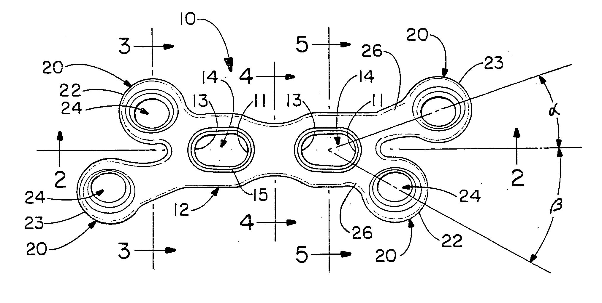
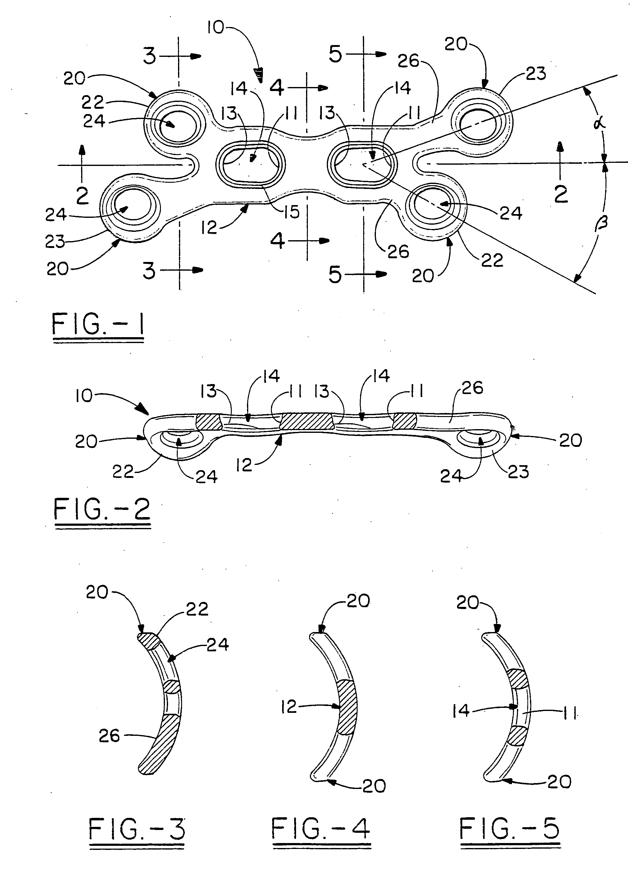
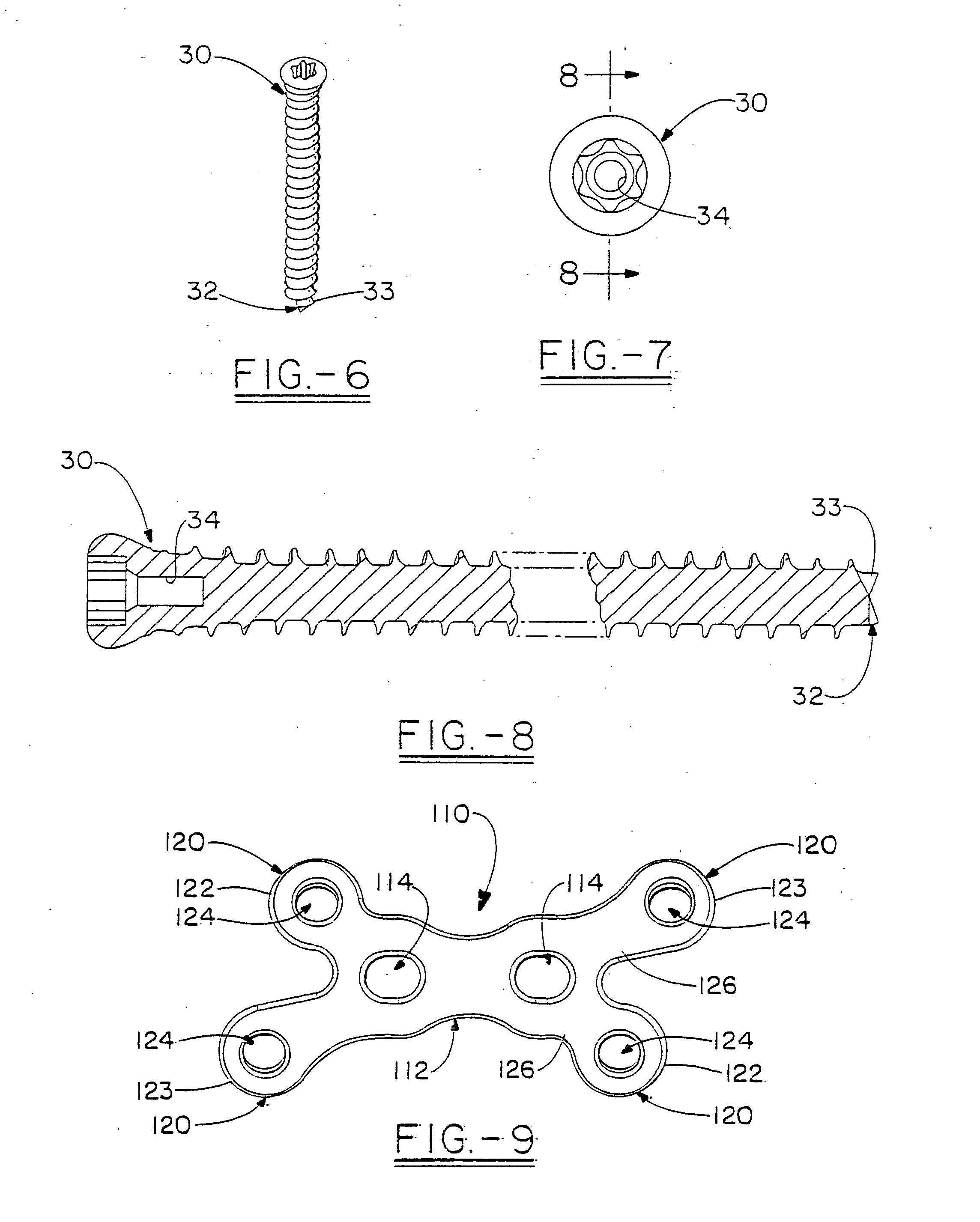
[0054]FIG. 9 is a plate in accordance with the present invention which is intended to provide greater stability in indications, such as use in the spine, or pelvis. This plate 110 shares the same features as the design show in FIG. 1, but is somewhat more robust, with less tapering in the waist areas 126 of the trunk portion 112. The plate includes opposing pairs of asymmetrical arms, 120, which can again be viewed as diagonal pairs 122, 123 of arms, each including a set of screw holes 124 The trunk area 112 further includes slotted screw holes 114 which can be similarly used to cause a compression between them. The bottom side is radiiused as for the small bone area, but with a gentler curvature of radius.

[0055]FIG. 10 is a beta version of the plate shown in FIG. 1. Thus, it is a mirror image of the plate, with corresponding elements such as a trunk portion 12′, a pair of angled arms 20′ at either end each having a screw hole 24′, and the trunk portion 12′ having two compression sl...

first embodiment

[0056]FIGS. 12 through 14 illustrate an embodiment of the plate 310,310′ with a shorter trunk 312,312′ that serves principally to join the two ends bearing the arms 320,320′ and including a single narrowed waist area 326,326′. The arms 320,320′ each include screw holes 324,324′ which are rounded and provide the option of conical multi-axis fixation as shown and described for the FIGS. 16 through 19 illustrate an embodiment of a plate 410,410′ having two opposing pairs of arms 420, 420′ each including the multi-axis screw hole 424 and having a relatively short trunk portion 412, 412′ having a single compression slot 414, 414′. FIGS. 20 through 23 illustrate both the alpha and beta version of an embodiment of the plate 510, 510′ which have the pairs of asymmetrical arms 520, 520′ and including a central trunk area 512, 512′ with three compression slots 514,514′ separated by narrowed waist areas 526, 526′. FIGS. 24 through 27 illustrate both the alpha and beta version of an embodiment...


PUM


Abstract

The present invention relates to an orthopedic plate and screw system and instruments for surgical fixation of a small bone or bones. The plate facilitates three dimensional contouring to provide for a variety of applications and to accommodate individual variation in bone shape. The plate has a modified x shape including a central trunk portion including one or more screw holes along a longitudinal axis and a set of divergent upper and an oppositely extending set of divergent lower arms, each arm including screw holes which are placed at a radially equal distance but which diverging asymmetrically from the longitudinal axis relative to its paired upper or lower mate. The screws of the system are self-starting, self-tapping screws including the option of partial or full cannulation.

Description

[0001] This application is based on U.S. Provisional Application Ser. No. 60 / 648,348 filed on Jan. 28, 2005[0002] The present invention relates to an orthopedic plate in particular for surgical repair or reconstruction of a small bone and to a system of orthopedic plates which are presented during surgery for use for a variety of indications. BACKGROUND OF THE INVENTION [0003] The field of orthopedic medicine has grown tremendously in the past fifty years as surgical techniques, implants and instrumentation have developed and been improved. The medical companies have tended to focus their attention on the largest market areas so that some areas of the body, such as the spine, knees and hips, have received intense focus from the large medical companies. While the small bones are frequently subject to the need for re-constructive surgery for example, as a result of trauma, to counteract the effects of aging or to repair congenital deformities, this area has typically not received the ...

Claims


Application Information

Patent Timeline
IPC IPC(8): A61F2/30
CPCA61B17/8061A61B17/8066A61B17/8085
Inventor KAY, DAVID B.STRNAD, LEE A.DUCHARME, DUSTINWYNKOOP, G. MARTIN
Owner WRIGHT MEDICAL TECH
Why Eureka
Try Eureka