Variable valve actuating mechanism with lift deactivation

Active Publication Date: 2010-11-25
MECHADYNE INT
View PDF5 Cites 7 Cited by
  • Summary
  • Abstract
  • Description
  • Claims
  • Application Information

AI Technical Summary

Benefits of technology

[0007]The invention employs a two part summation lever design, which allows the followers for the two different cam profiles to move independently from one another. It also provides a latch mechanism for locking the two parts together. The key feature of the design is that it allows the control spring to act as a lost motion spring whilst the valve lift is deactivated, as well as controlling the movement of the summation lever to ensure that its cam follower(s) maintain contact with one of the cam profiles at all times. By combining the functions of the lost-motion spring required by a deactivation system and the control spring required by a cam summation system, the invention enables valve deactivation to be achieved with a minimum of additional complexity.
[0008]Incorporating a valve deactivation system into the summation lever is advantageous in that it allows the mass of the moving components to be minimised whilst the valve is deactivated. The disadvantage of using the summation lever is that it is difficult to find space for a sufficiently strong lost motion spring, and if such a spring were to be integrated with the actuating rocker, it would significantly add to the valve train mass during normal operation when the valve lift is activated.

Problems solved by technology

The disadvantage of using the summation lever is that it is difficult to find space for a sufficiently strong lost motion spring, and if such a spring were to be integrated with the actuating rocker, it would significantly add to the valve train mass during normal operation when the valve lift is activated.

Method used


Image

  • Variable valve actuating mechanism with lift deactivation
  • Variable valve actuating mechanism with lift deactivation
  • Variable valve actuating mechanism with lift deactivation

Examples


first embodiment

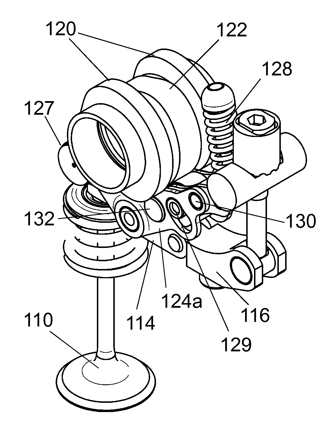
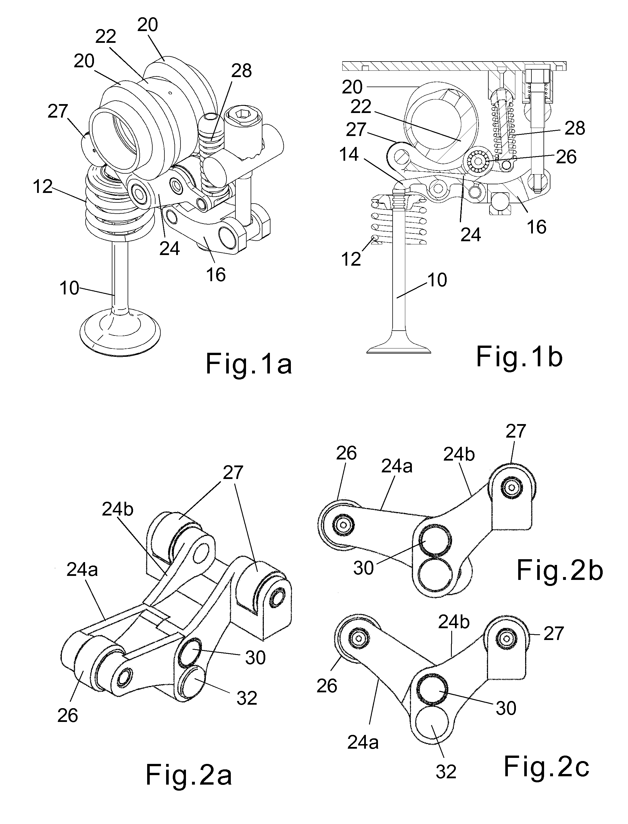
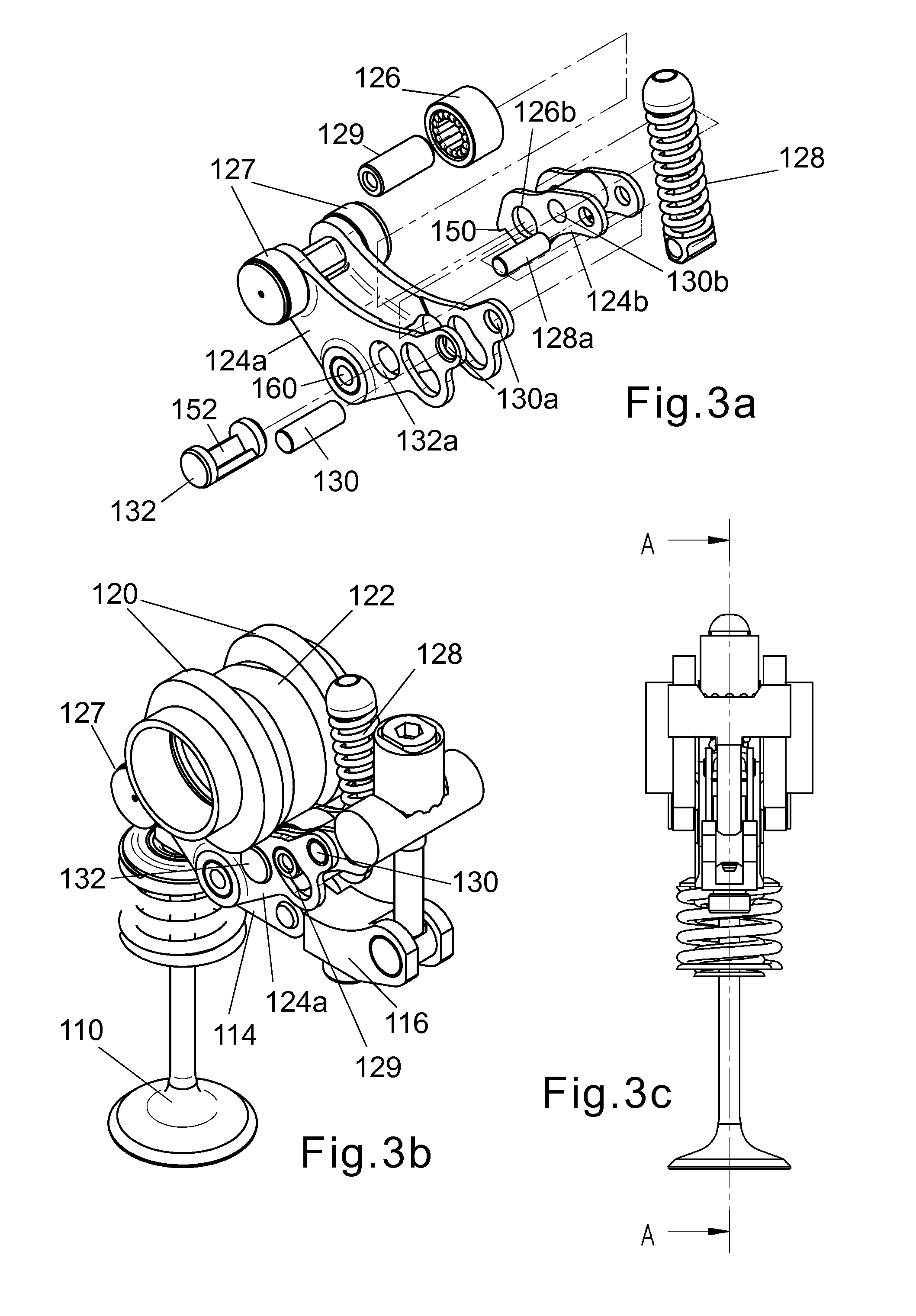
[0032]FIGS. 3, 4 and 5 show the invention which demonstrates how the invention may be applied to the valve train of FIG. 1. The summation lever is constructed in two parts 124a and 124b, that can move relative to one another. The first part 124a is supported by the valve actuating rocker 114 by means of a pivot 160 and carries a pair of cam followers 127 that contact the cam profiles 120. The second part 124b of the summation lever is connected to the first 124a by a pivot pin 130 received in holes 130a in the first part 124a and a hole 130b in the second part. The second part 124b carries a single cam follower roller 126, which is rotatable about an axle pin 129 and contacts the second cam profile 122. The second part 124b of the summation lever is also connected by a pin 128a received in holes in the second part 124b to the control spring 128 which controls the motion of the summation lever while the valve is closed.

[0033]The summation lever assembly also contains a latch mechanis...

third embodiment

[0047]The embodiment of FIG. 11 uses a similar latching pin 483 to the third embodiment described above, but the deactivation lever 481 forms part of an interlock mechanism such that it can only move at one point in the valve lift cycle. In this case, forked members 487 straddling the ends of the pin 483 are secured for rotation with the deactivation levers 481. The pivot shaft 460 connecting the valve actuator 414 to the summation lever 424a is fixed for rotation with the summation lever 424a and has a profiled cut-out 491 in one end that engages with an interlock pin 489 on the deactivating lever 481. FIG. 11a shows the interlock pin positioned outside the cut-out 491 in the pivot shaft such that the valve lift is activated. FIG. 11d on the other hand shows the interlock pin 489 engaged in the cut-out 491 in the pivot shaft 460 such that the valve lift is deactivated.

[0048]The profile of the cut-out 491 in the pivot shaft 460 prevents the interlock pin 489 from moving freely betwe...


PUM


Abstract

An internal combustion engine is described having a valve mechanism that comprises two cams (120,122) mounted coaxially and a summation lever (124) having cam followers (126, 127) in contact with both cams so as to move in proportion to the instantaneous sum of the lifts of the respective cams. A control spring (128) is provided to maintain contact between one cam profile and its respective follower(s), and a valve actuator (114) opens the engine valve (110) in dependence upon the movement of the summation lever, thereby enabling so as to enable the valve timing, valve lift and valve event duration to be adjusted by varying the phases of the two cams. In the invention, the summation lever is constructed in two parts (124a, 124b) that can be selectively locked and unlocked to allow the valve lift to be deactivated and the motion of both parts is controlled by the control spring (128) when the two parts of the summation lever are unlocked from one another.

Description

FIELD OF THE INVENTION[0001]The invention relates to an internal combustion engine having a valve actuating mechanism that comprises two cams mounted coaxially, a summation lever having at least one cam follower in contact with each respective cam and movable in proportion to the instantaneous sum of the lifts of the two cams, a control spring acting to maintain one cam in contact with each follower associated therewith, and a valve actuating rocker serving to open an engine valve in dependence upon the movement of the summation lever, the timing, lift and duration of each valve event being adjustable by varying the phases of the two cams.BACKGROUND OF THE INVENTION[0002]An internal combustion engine as set out above is described in the Applicants' earlier GB Patent Application No. 0708967.5. In the accompanying drawings, FIG. 1a is a perspective view of a valve actuating mechanism as described in the latter patent application and FIG. 1b is a section through the same mechanism. A p...

Claims


Application Information

Patent Timeline
IPC IPC(8): F01L1/34
CPCF01L1/18F01L1/267F01L2105/00F01L13/0047F01L13/0005F01L2305/00
Inventor METHLEY, IAN
Owner MECHADYNE INT
Why Eureka
Try Eureka