Energy storage and generation system for an electrically powered motorized vehicle

Inactive Publication Date: 2011-03-24
ANANTHAKRISHNA ANIL
View PDF5 Cites 10 Cited by
  • Summary
  • Abstract
  • Description
  • Claims
  • Application Information

AI Technical Summary

Benefits of technology

[0011]The flywheel assembly also includes a drive control unit connected to one or more sensors for obtaining feedback information on a magnetic field polarity of the permanent magnets on the rotary member and to the field coils for generating magnetic field in the field coils of the fixed member in response thereto to rotate the rotary member. The rotation of the rotary member stores rotational kinetic energy due to the dead weight of the plurality of batteries which in turn is applied to the power wheels of the electrically powered motorized vehicle to accelerate the electrically powered motorized vehicle to a speed equal to a predetermined vehicle speed from a standing start.

Problems solved by technology

This is due to constant increase in gasoline fuel prices, the exhaustion of the gasoline fuel resources and also other environmental effects by internal combustion exhaust.
In the automobile industry, many attempts have been made in this regard to develop an effective free-ranging electrically powered motorized vehicle, however, the success rate in achieving the same is very low due to certain limitations.
In a conventional electrically powered motorized vehicle, the use of rechargeable storage batteries restricts the available power output and range of the vehicle due to dead weight of such batteries.
Moreover, the costs of batteries are relatively high which in turn increases the cost of the vehicle.
Further, the battery life is another concern as it impacts the economy of the battery powered vehicle, as the replacement cost of the battery is another essential factor.
In addition, the conventional flywheels used in the electrically powered motorized vehicles which stores energy mechanically in the form of kinetic energy have low specific energy.
There are safety concerns associated with said flywheels due to their high speed rotor and the possibility of it breaking loose and releasing all its energy in an uncontrolled manner.
The conventional flywheels are a less mature technology than chemical batteries and the current cost is too high to make them competitive in the market.
The approach conventionally taken has been to add a flywheel device to a drive system is prone to said limitations.
In addition, the conventional materials like iron cast, steel and other metal alloys used for manufacturing flywheels and also the coupling of the flywheel separately to the vehicle crankshaft amounts to adding weight to the vehicle.
Hence, this may lead to increase in the cost of assembling the vehicle, its maintenance and also decrease in the efficiency.

Method used


Image

  • Energy storage and generation system for an electrically powered motorized vehicle
  • Energy storage and generation system for an electrically powered motorized vehicle
  • Energy storage and generation system for an electrically powered motorized vehicle

Examples


Embodiment Construction

[0017]An energy storage and generation system for an electrically powered motorized vehicle is disclosed. The following description is merely exemplary in nature and is not intended to limit the present disclosure, applications, or uses. It should be understood that throughout the drawings, corresponding reference numerals indicate like or corresponding parts and features.

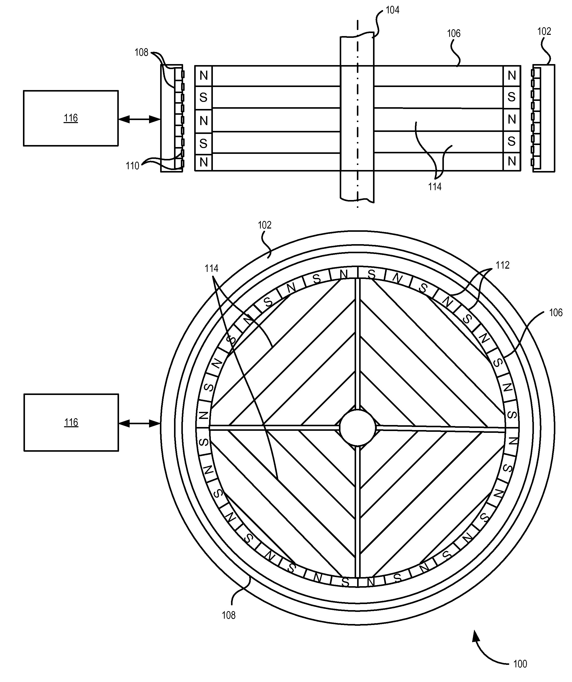
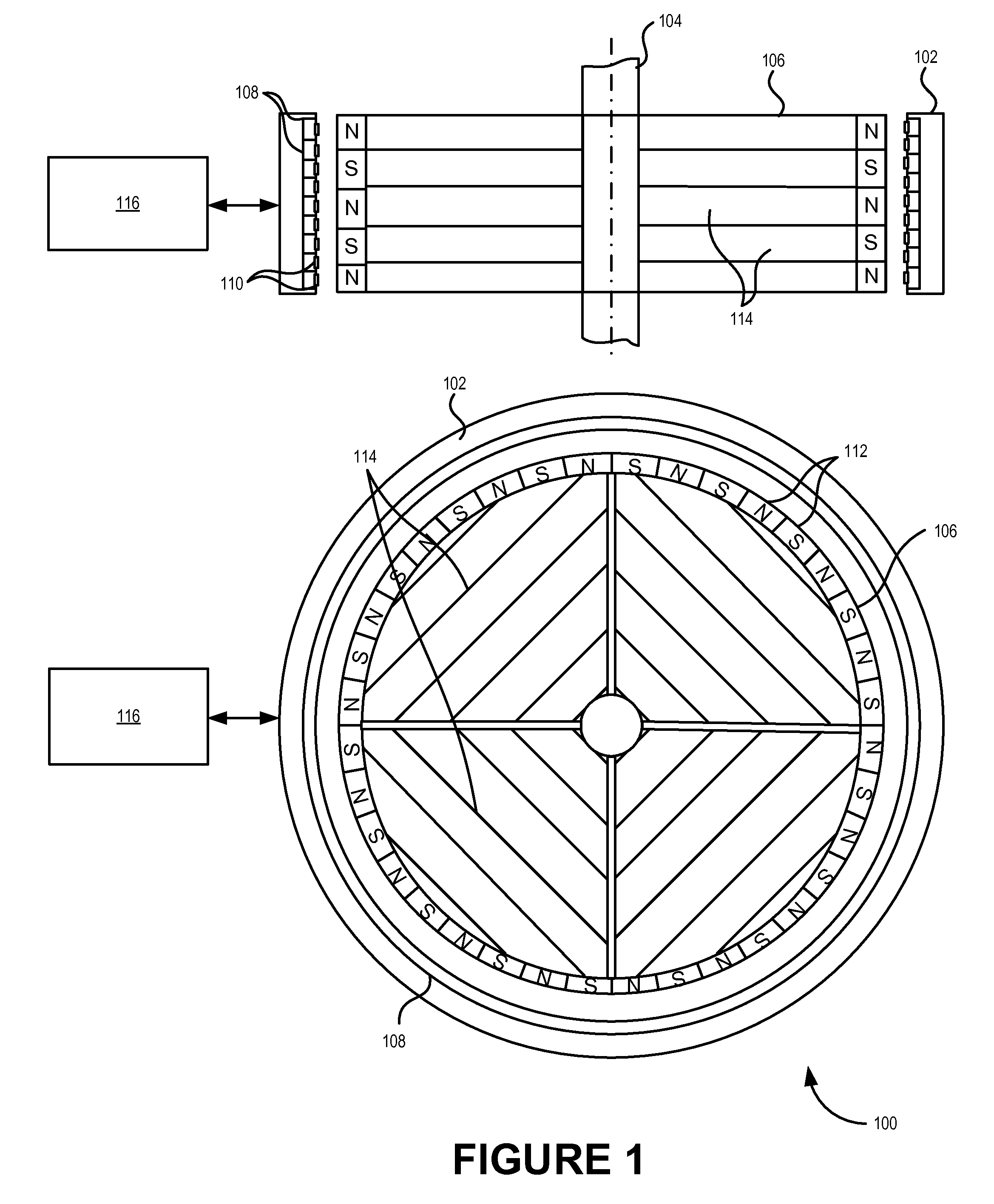
[0018]FIG. 1 illustrates cross-sectional views of an energy storage and generation system 100 for an electrically powered motorized vehicle, according to one embodiment. The energy storage and generation system 100 includes a stator 102, a shaft 104, a rotor 106 carried on the shaft 104, and a drive control unit 116. The stator 102 consists of field coils 108 provided on the inner periphery of the stator 102. The stator 102 is mounted on the chassis of the electrically powered motorized vehicle and may be electric powered.

[0019]The rotor 106 consists of permanent magnets 112 with N and S poles arranged alternately ...


PUM


Abstract

An energy storage and generation system for an electrically powered motorized vehicle is disclosed. In one embodiment, an energy storage and generation system for an electrically powered motorized vehicle includes a stator having field coils and sensors which are provided on the inner periphery of the stator, and a rotor having permanent magnets with N and S poles arranged alternately in a circumferential direction on the outer periphery to face the field coils and housing batteries of the electrically powered motorized vehicle. The energy storage and generation system also includes a drive control unit connected to the sensors and the field coils for generating magnetic field in the field coils of the stator in response thereto to rotate the rotor. The rotation of the rotor stores rotational kinetic energy due to the dead weight of the plurality of batteries which is used to propel the electrically powered motorized vehicle.

Description

CLAIMS OF PRIORITY[0001]Benefit is claimed under 35 U.S.C. 119(e) to U.S. Provisional Application Ser. No. 61162238, entitled “FLYWHEEL POWER SYSTEM IN AN ELECTRIC VEHICLE” by Anil Ananthakrishna, filed on Mar. 20, 2009, which is herein incorporated in its entirety by reference for all purposes.FIELD OF TECHNOLOGY[0002]Embodiments of the disclosure generally relate to the field of electrically powered motorized vehicles, and more particularly to an energy storage and generation system in an electrically powered motorized vehicle.BACKGROUND[0003]The need to conserve non-renewable energy resource and clean-running vehicles has been echoing for many years. This is due to constant increase in gasoline fuel prices, the exhaustion of the gasoline fuel resources and also other environmental effects by internal combustion exhaust. In general, the need to conserve natural resources, to avoid contamination of the environment as well as economic factors, has led to an increasing emphasis on th...

Claims


Application Information

Patent Timeline
IPC IPC(8): H02K7/02
CPCB60K1/04B60K7/0007B60L11/16B60L11/1816H02K7/006Y02T10/6204Y02E60/16Y02T10/641Y02T10/7005Y02T10/7033Y02T90/14H02K7/025B60L7/12B60L15/2009B60L50/30B60L50/52B60L50/64B60L50/66B60L53/14B60L58/21B60L2220/44B60L2220/50B60L2240/12B60L2240/463B60L2240/545B60L2260/26Y02T10/62Y02T10/64Y02T10/70Y02T10/7072Y02T10/72
Inventor ANANTHAKRISHNA, ANIL
Owner ANANTHAKRISHNA ANIL
Why Eureka
Try Eureka