Image stabilization circuitry for liquid lens

Active Publication Date: 2010-11-25
INVENIOS FRANCE SAS
View PDF8 Cites 108 Cited by
  • Summary
  • Abstract
  • Description
  • Claims
  • Application Information

AI Technical Summary

Benefits of technology

[0010]It is an aim of embodiments of the present invention to provide a lens that at least partially address one or more the prior art.

Problems solved by technology

While separate liquid lenses could be used for each of these functions, such a solution is disadvantageous due to its size.

Method used


Image

  • Image stabilization circuitry for liquid lens
  • Image stabilization circuitry for liquid lens
  • Image stabilization circuitry for liquid lens

Examples


Embodiment Construction

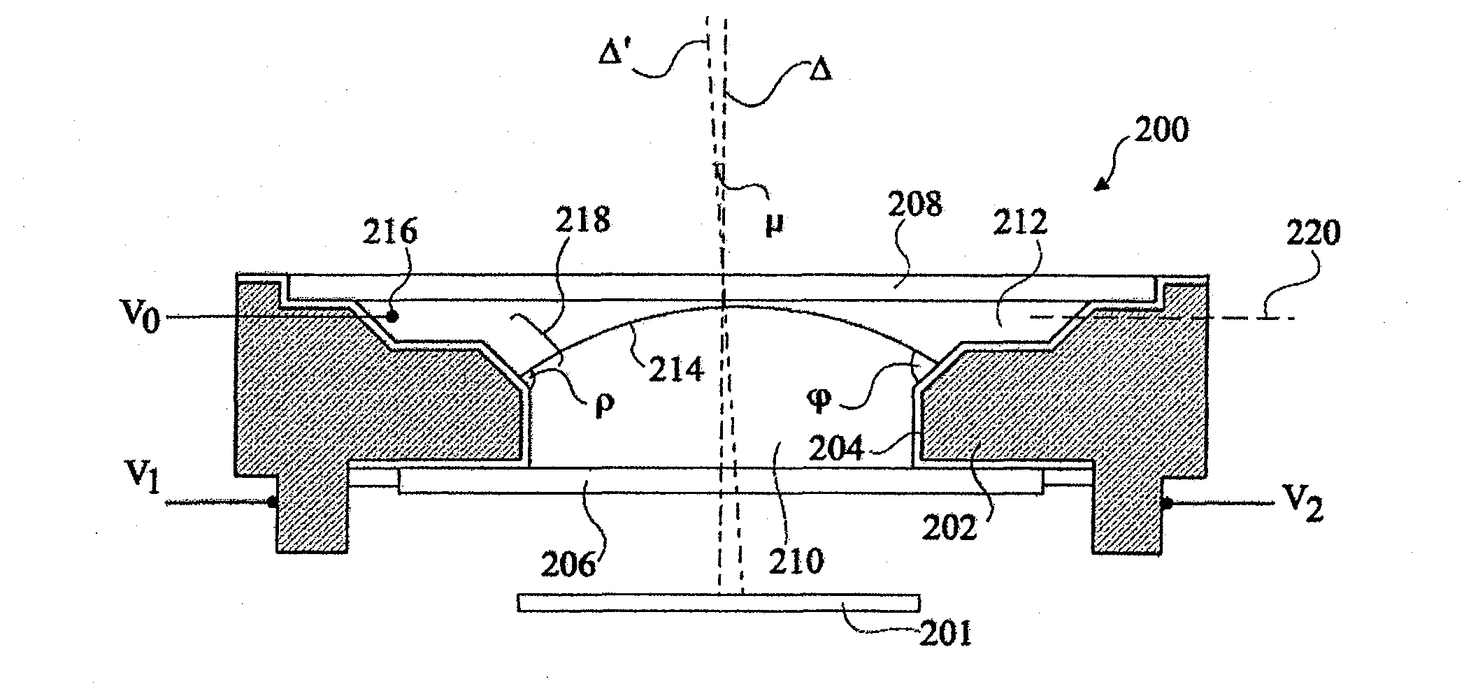
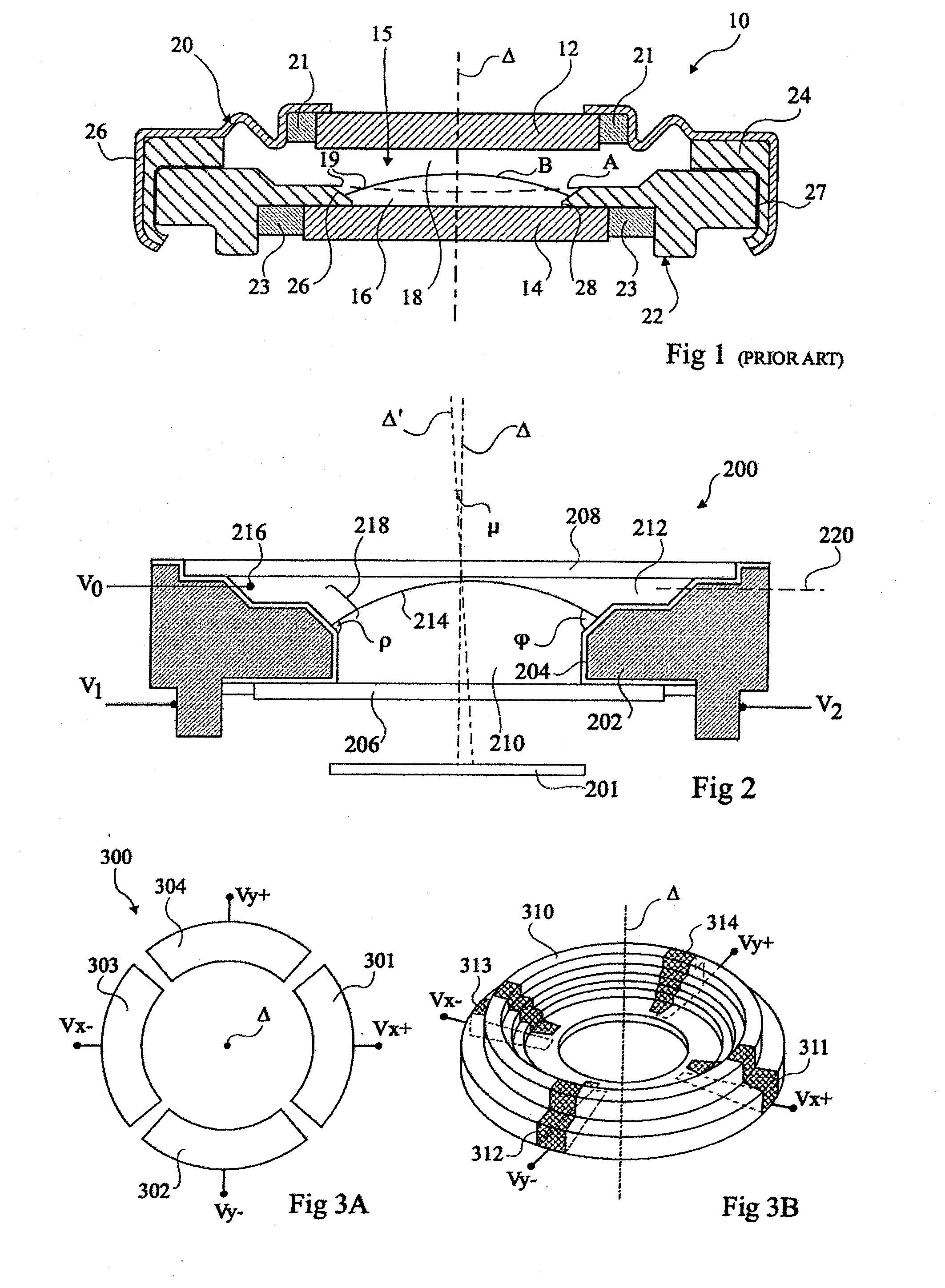
[0042]FIG. 2 is a cross-section view schematically illustrating a liquid lens 200, and showing how a tilt and focus can be achieved by application of different voltages V1 and V2 to an electrode 202.

[0043]Liquid lens 200 is mounted over an image sensor 201, for example with one or more fixed lenses positioned between the liquid lens 200 and the image sensor (fixed lenses not shown in FIG. 2). Lens 200 comprises an annular body 202, having an insulating layer 204 covering its inner surfaces, such that it is insulated from the liquids in the lens. Transparent windows 206, 208 are glued to an underside and a top side respectively of the annular body 202, sealing an insulating liquid 210 and a conducting liquid 212 in the lens. These liquids have different refractive indices, and form an optical interface 214 in the form of a meniscus where they meet.

[0044]The annular body 202 either comprises a segmented electrode or a resistive body, such that when two different voltages V1 and V2 are...


PUM


Abstract

A method of controlling a liquid lens in an imaging device, the liquid lens including a liquid-liquid interface between first and second immiscible liquids deformable by electrowetting; a chamber containing the first and second liquids, the first liquid being an insulating liquid and the second liquid being a conducting liquid; and a first electrode in contact with the second liquid and at least one second electrode insulated from the second liquid by an insulating layer, the first and second electrodes being arranged to allow a plurality of voltages levels to be applied between the first and second electrodes to control the curvature of the liquid-liquid interface, the method including: determining motion data representative of a movement of the imaging device; determining focusing data representative of a desired focus of the imaging device; determining the plurality of voltage levels to be applied between the first and second electrodes, wherein each of the voltage levels is a function of the motion data, the focusing data and at least one parameter relating to the liquid lens and preliminary determined in a calibration phase.

Description

FIELD OF THE INVENTION[0001]The present invention relates to circuitry for controlling a liquid lens, and in particular to image stabilization circuitry for a liquid lens.BACKGROUND OF THE INVENTION[0002]Electrowetting devices, and in particular electrowetting lenses, are known in the art, and generally comprise a refractive interface between first and second immiscible liquids that is movable by electrowetting.[0003]FIG. 1 represents FIG. 4 of European Patent Application EP 1662276, and illustrates a variable focus lens 10 according to one example of the prior art. Lens 10 comprises two transparent windows 12, 14, arranged in parallel and facing each other, and delimiting, in part, an internal volume containing two immiscible liquids 16, 18, with different optical indices. Where the two liquids meet they form an optical interface 19 in the form of a meniscus, which can have a number of different shapes, examples being shown by lines A and B. The liquids 16, 18 have substantially eq...

Claims


Application Information

Patent Timeline
Patent Type & Authority Applications(United States)
IPC IPC(8): H04N5/225
CPCG02B3/14G02B26/005G02B27/646H04N5/23287H04N5/23248H04N5/23258H04N5/2254H04N23/55H04N23/67H04N23/68H04N23/6812H04N23/687
Inventor BERGE, BRUNO
Owner INVENIOS FRANCE SAS
Why Eureka
Try Eureka