
Controls for ventilation and exhaust ducts and fans

a technology of control and ventilation duct, which is applied in the direction of ventilation systems, heating types, and domestic stoves or ranges, etc., can solve the problems of increased power consumption, ineffective or inefficient fume and/or smoke extraction, and excessive use of fans

Inactive Publication Date: 2010-11-25
SO
View PDF20 Cites 24 Cited by
  • Summary
  • Abstract
  • Description
  • Claims
  • Application Information

AI Technical Summary

Benefits of technology

[0023]The valve assembly may be located at, adjacent or near an outlet end of the ducting or at a boundary of zones of the environmental space. The exhaust apparatus may further comprise a hood, the hood having a control panel. The control panel may comprise a reset control for resetting the at least one detector, releasing the brake of the fan assembly, and moving the valve member to the first position. The exhaust apparatus may further comprise at least one sensor for controlling t

Problems solved by technology

Such a situation can lead to ineffective or inefficient fume and / or smoke extraction, and / or excess use of the fan and therefore increased power consumption.
Increased power consumption leads to increased energy costs.
Such a level of use is very wasteful of energy and increases operational costs.
Such systems do not operate in the presence of noxious gasses or fumes, or when the carbon dioxide and / or carbon monoxide level increases and the oxygen level decreases in the ambient air.
Also, there is a tendency for the ducting to act as a conduit for fire if the premises are on fire, or for contaminants in the ducting to catch fire.
Also each damper operates independently and there is no structured approach to use and operation of the dampers, and duct fans, for prevention of the spread of fire.

Method used


Image

  • Controls for ventilation and exhaust ducts and fans
  • Controls for ventilation and exhaust ducts and fans
  • Controls for ventilation and exhaust ducts and fans

Examples


Embodiment Construction

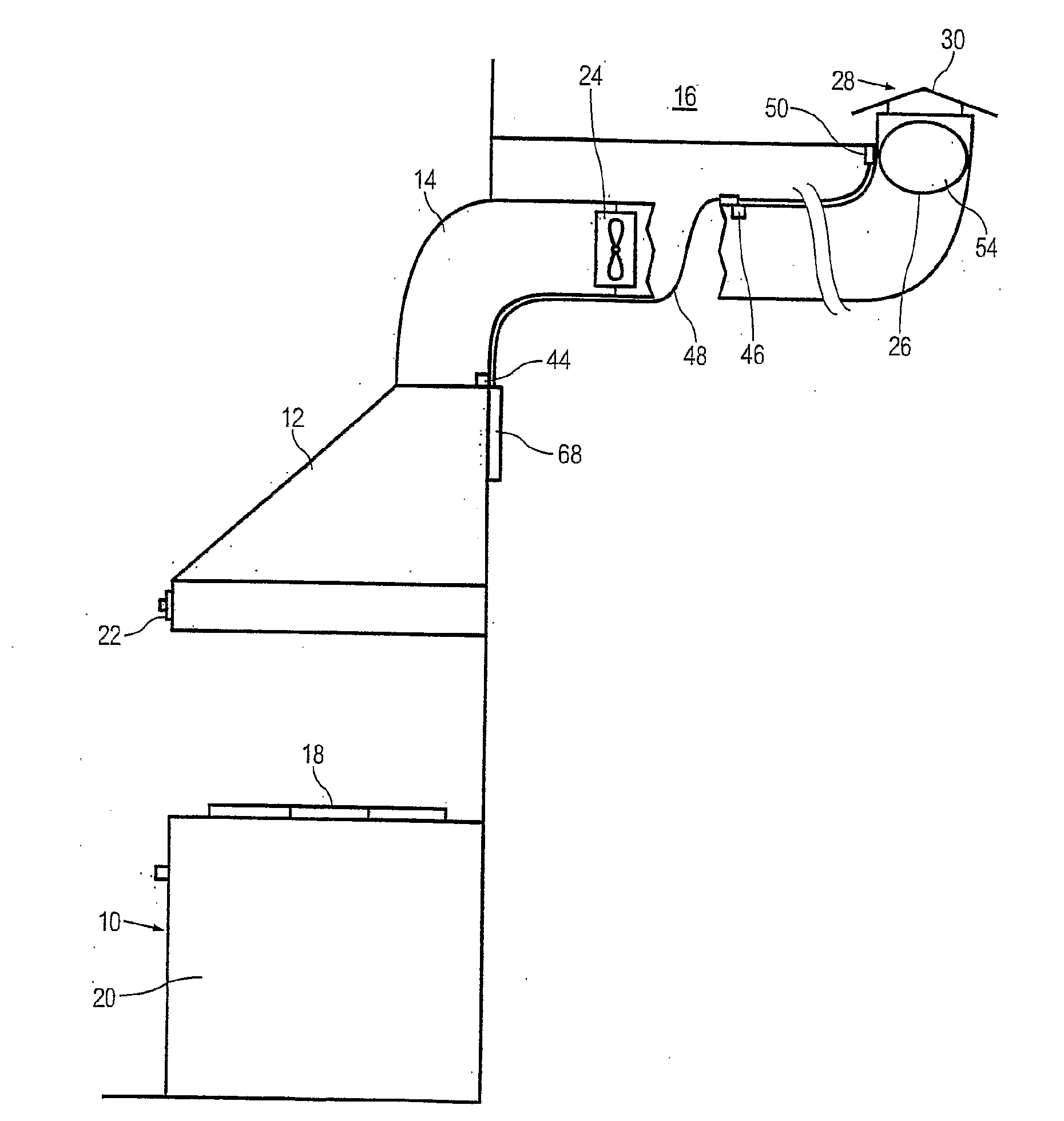
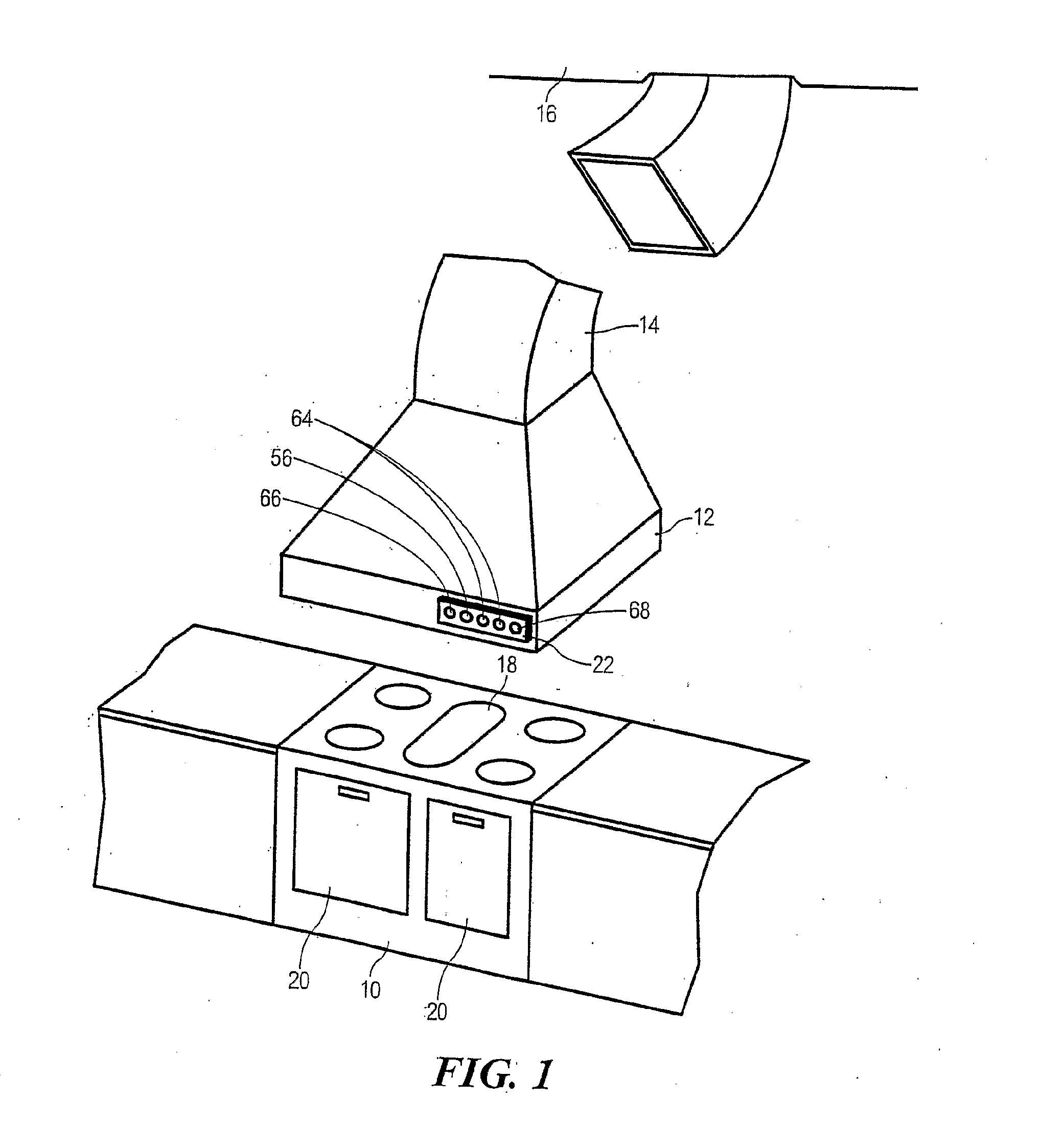
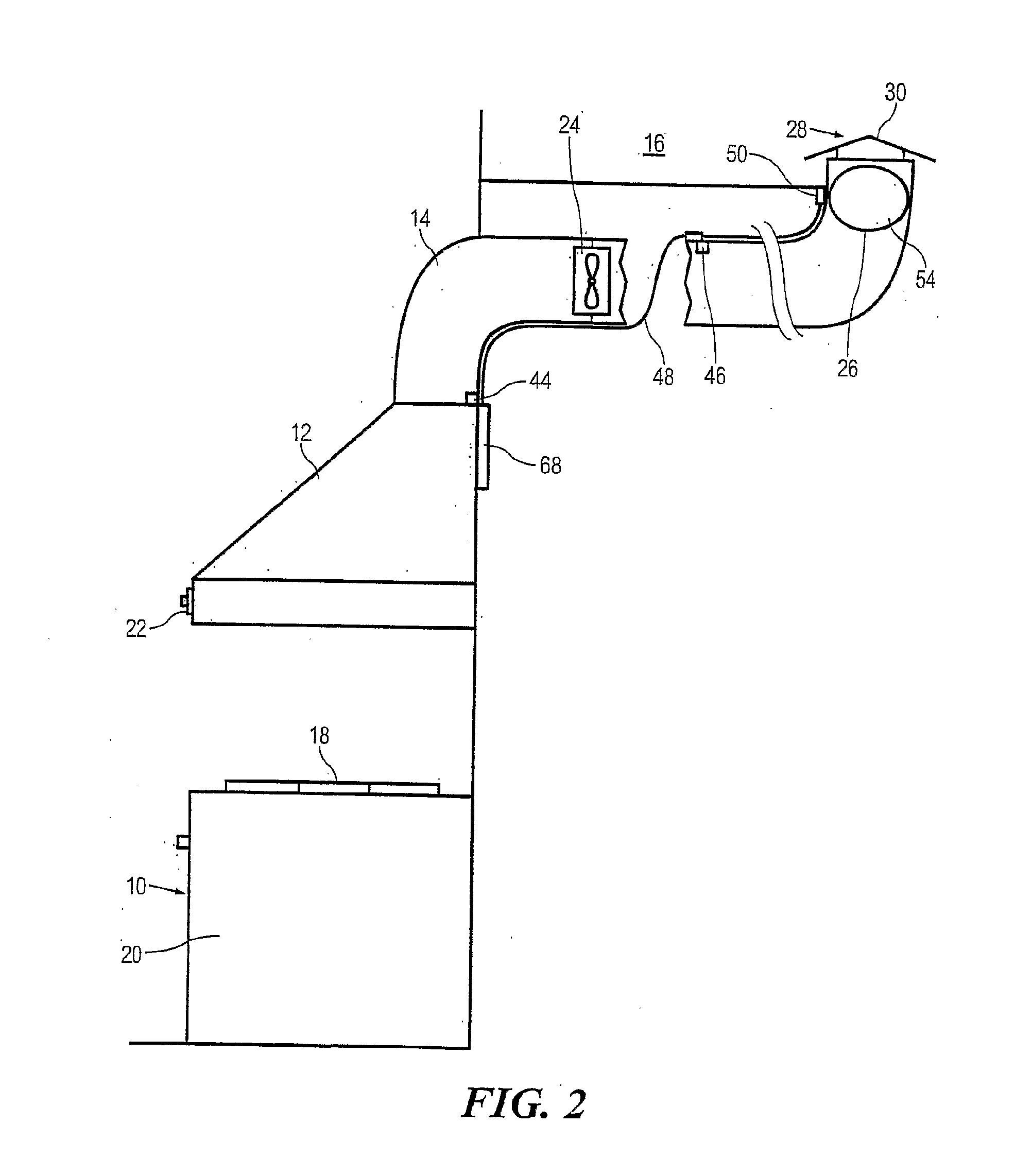
[0046]To refer to FIGS. 1 and 2, there is illustrated a commercial stove 10 with an exhaust hood 12. Ducting 14 connects the exhaust hood 12 to the outside atmosphere 16. Although a stove 10 is shown, it could be any commercial or industrial equipment that produces or uses smoke and / or fumes and / or noxious gasses, a car park for removing vehicle exhaust fumes, and so forth.

[0047]The stove 10 has hobs 18 for use in the cooking of food, and are or more ovens 20 also used in the cooking of food.

[0048]The exhaust hood 12 has a control panel 22 for controlling the operation of the exhaust hood 12, including the operation of a fan assembly 24. Although a single fan assembly 24 is shown, there may be two or more fan assemblies. The fan assembly 24 may be of any suitable form or nature. Preferably, the fan assembly 24 is multiple speed.

[0049]Also in ducting 14 is a valve 26 that is shown in the open position in FIG. 2, and which is adjacent the outlet end 28 of the ducting 14. The outlet en...


PUM


Abstract

A ventilation or exhaust system, having ducting, and a fan assembly for placement in ducting of a ventilation or exhaust system for an environment space. The fan assembly has a motor having an output shaft, a fan mounted on the output shaft, and a brake mounted for operation on the motor. The brake is operable for stopping rotation of the motor upon a detection of a prescribed situation one or more of: the environmental space, and the ducting. Also included is a valve assembly having a valve member for placement in the ducting for movement between a first position where the ducting is substantially open, and a second position where the ducting is substantially closed. The valve member is adapted to move from the first position to the second position in response to at least one detection of a prescribed situation. At least one detector is provided for detecting a prescribed situation, the detector being for controlling the operation of the brake of the fan assembly, and the valve assembly, in response to the detecting.

Description

FIELD OF THE INVENTION[0001]This invention relates to controls for ventilation and exhaust ducts and fans and preferably, through not exclusively, relates to such an apparatus for use in offices, commercial kitchens, factories, warehouses, retail centres, production facilities, car parks, cooling tower fans, or the like.BACKGROUND OF THE INVENTION[0002]Exhaust apparatus for fumes and / or smoke are normally used in commercial kitchens, factories, production facilities, car parks, cooling tower fans or the like, to exhaust fumes and / or smoke and / or gasses caused by the cooking or production process, or vehicle exhausts. Some exhaust systems may have a hood above the stove or production facility, and ducting to connect the hood to the outside atmosphere. One or more fans are built into the ducting or the hood to force the fumes and / or smoke through the ducting. Filters may be used to remove the principal contaminants from the fumes and / or smoke.[0003]The fan or fans are normally control...

Claims


Application Information

Patent Timeline
IPC IPC(8): F24F7/007F24F7/00F04B35/04
CPCF24C15/2021F24F2007/001F24F7/06
Inventor SO
Owner SO
Learn More