Automatic control of a large bale loading apparatus

a bale loading and automatic control technology, applied in the field of agricultural bale handling and hauling machines, can solve the problems of increasing the cost of manual handling of bales, high labor requirements, and the abandonment of a growing number of commercial growers

a bale loading and automatic control technology, applied in the field of agricultural bale handling and hauling machines, can solve the problems of increasing the cost of manual handling of bales, high labor requirements, and the abandonment of a growing number of commercial growers

US20100299029A1Active Publication Date: 2010-11-25BLUE LEAF I P INC

Image

  • Automatic control of a large bale loading apparatus
  • Automatic control of a large bale loading apparatus
  • Automatic control of a large bale loading apparatus

Examples


Embodiment Construction

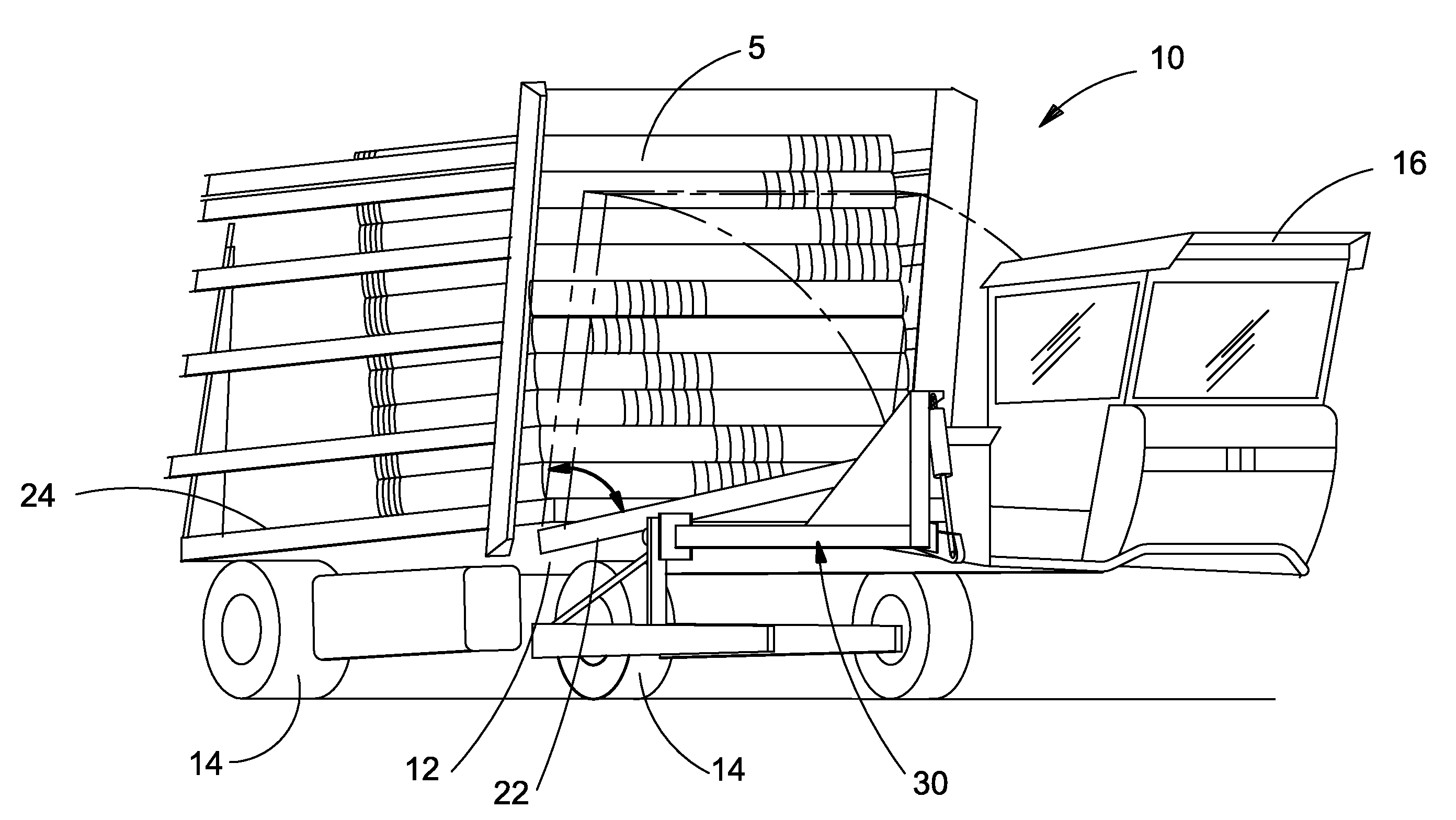
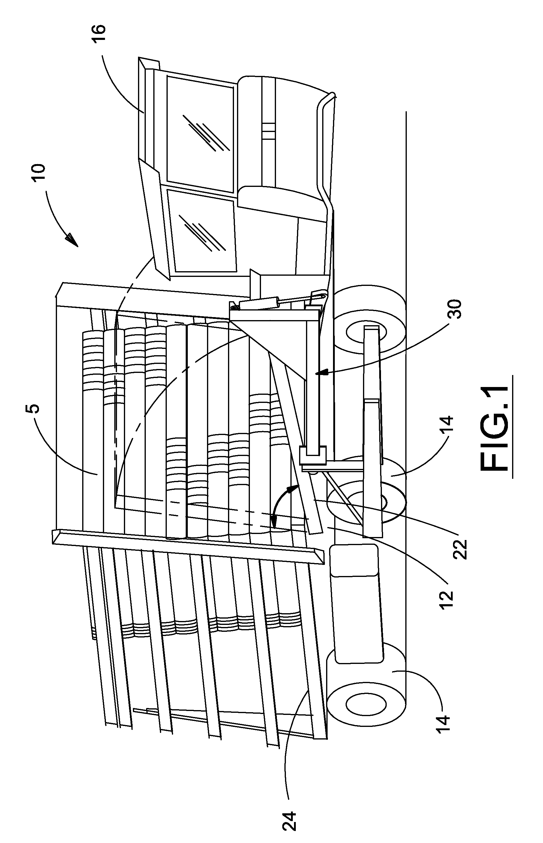
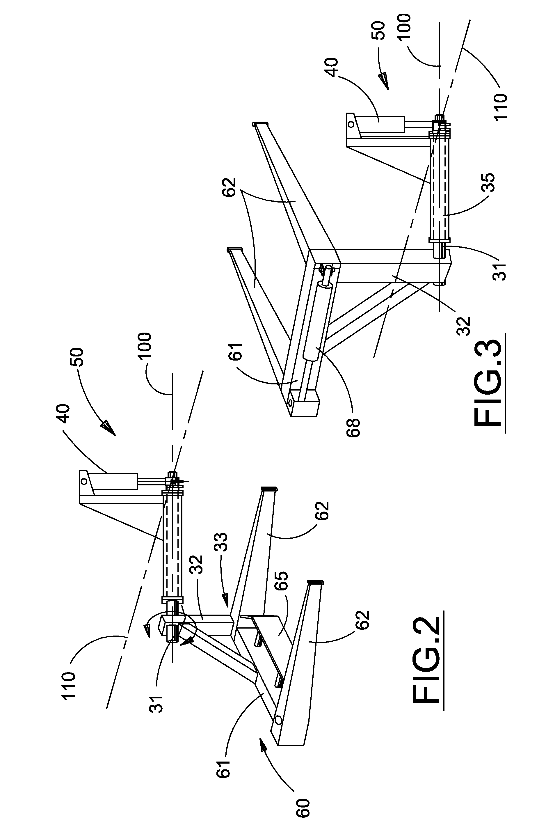
[0027]Many of the fastening, connection, processes and other means and components utilized in this invention are widely known and used in the field of the invention described, and their exact nature or type is not necessary for an understanding and use of the invention by a person skilled in the art, and they will not therefore be discussed in significant detail. Also, any reference herein to the terms “left” or “right” are used as a matter of mere convenience, and are determined by standing at the rear of the machine facing in its normal direction of travel. Likewise, “forward” and “rearward” are determined by the normal direction of travel. “Upward” and “downward” orientations are relative to the ground or operating surface as are any references to “horizontal” or “vertical” planes. Furthermore, the various components shown or described herein for any specific application of this invention can be varied or altered as anticipated by this invention and the practice of a specific app...


PUM


Abstract

A control system for managing rotation of a bale loading arm in a bale loader in which a pair of sensors combined with a purposefully designed sensor target enable loading arm position to be efficiently derived by a controller in order to direct the actuator movements based upon loading arm position necessary for automated operation of a bale loading cycle. Additional inputs to the controller enable initiation of a bale loading cycle to be automatically initiated. The controller may also determine when a complete bale wagon load is achieved and automatically direct loading arm motions necessary to configure the bale wagon for transport.

Description

BACKGROUND OF THE INVENTION[0001]The present invention relates generally to agricultural bale handling and hauling machines, and more particularly to such a control system for a bale wagon that automates the loading of large bales onto a bale wagon.[0002]A large proportion of the resources and time of the agricultural industry is directed toward the production of feed for animals, and most specifically to the production of baled stem and leaf crops such as hay. The conventional process is to cut and condition the crop with a windrower, deposit it on the ground to dry, bale the crop when appropriately dry, and then position the bales in stacks for storage or transportation. High labor requirements and increasing costs of manual handling of bales have caused a growing number of commercial growers to abandon their small square bale operation for a large bale package, such as round bales, or large rectangular bales 3′×3′, 3′×4′, or 4′×4′ in cross-section. Due to the large size of the ba...

Claims


Application Information

Patent Timeline
25 Nov 2010
Publication
US20100299029A1
IPC
G06F19/00
CPC
A01D90/08
Inventors
FACKLER, ROBERT L.; WHITENIGHT, DONALD R.