Floating dock and dock unit for making such

a technology for floating docks and dock units, which is applied in the direction of floating buildings, pontoons, hull decks, etc., can solve the problems of limiting the movement of the cover with respect to the floating body, and achieve the effect of reducing one or more disadvantages

Active Publication Date: 2010-12-02
CANDOCK
View PDF30 Cites 33 Cited by
  • Summary
  • Abstract
  • Description
  • Claims
  • Application Information

AI Technical Summary

Benefits of technology

[0005]It is an object of the present invention to provide a dock unit and a floating dock made of such dock units that overcomes or mitigates one or more disadvantages of known dock units and floating docks made of such dock units or at least provides a useful alternative.
[0006]According to an aspect of the invention, there is provided a dock unit attachable to another dock unit with a fastener for forming a floating dock. The dock unit comprises a floating body and a cover. The floating body has a mating surface and an attachment adapted to receive the fastener and thereby attaching the floating body to the other dock unit. The cover covers the mating surface. The cover has a contact surface adapted to contact the fastener. In use, the contact surface is positioned proximate the attachment so that, when the attachment receives the fastener, the contact surface is contacted by the fastener, thereby limiting the movement of the cover with respect to the floating body.
[0009]According to another aspect of the invention, there is provided a cover for covering a mating surface of a floating body assembled to another floating body with a fastener for forming a floating dock. The cover comprises four lateral cover sides defining four cover corners. The cover further comprises a top surface for forming the floor of the floating dock and four protrusions, each one of the four protrusions being operative to abut against the floating body for supporting the top surface at a distance from the floating body. Each one of the four protrusions are located at a different one of the four cover corners. Thereby, a passage between the top surface and the floating body is created, providing access to at least two of the four lateral cover sides. The cover further comprises four contact surfaces, each one of the four contact surfaces comprising a conical portion having a symmetry axis substantially normal to the top surface. Each one of the four contact surfaces are located at a different one of the four cover corners so that when the fastener attaches the floating body to the other floating body, one of the four contact surfaces is contacted by the fastener, thereby limiting the movement of the cover with respect to the floating body.

Problems solved by technology

In use, the contact surface is positioned proximate the attachment so that, when the attachment receives the fastener, the contact surface is contacted by the fastener, thereby limiting the movement of the cover with respect to the floating body.

Method used


Image

  • Floating dock and dock unit for making such
  • Floating dock and dock unit for making such
  • Floating dock and dock unit for making such

Examples


Embodiment Construction

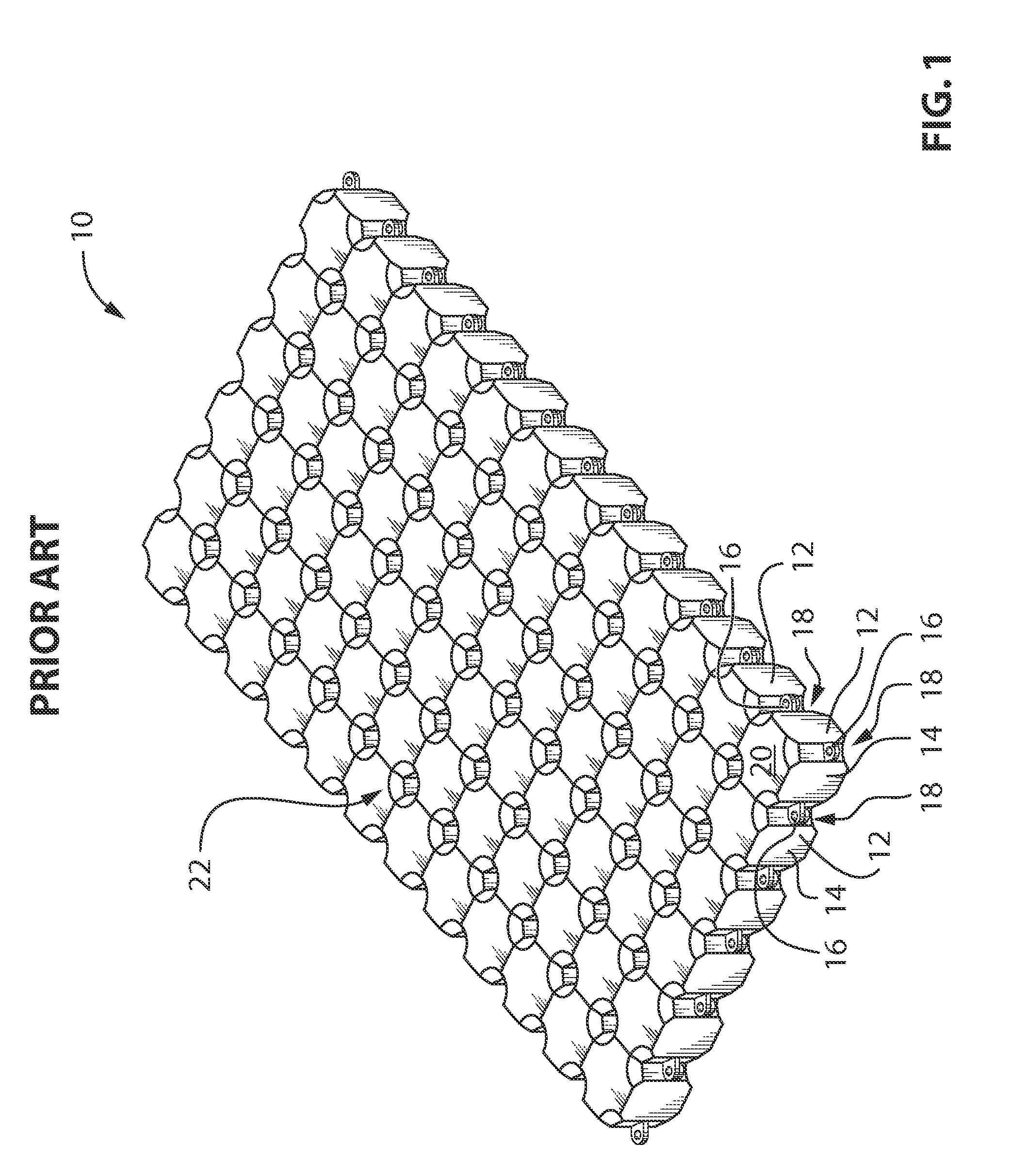
[0029]Referring to the drawings, and more particularly to FIG. 1 which shows a floating dock 10 according to the prior art. The floating dock 10 consists of several columns and rows of dock units 12 attachable to one another. Each dock unit 12 comprises a floating body 14 having an attachment 16 located at each body corner 18. At each location where at least two attachments 16 are aligned, a fastener, not shown, is inserted in the two attachments 16, attaching the floating bodies 14 together. A top surface 20 forms a portion of a floor 22 of the floating dock 10.

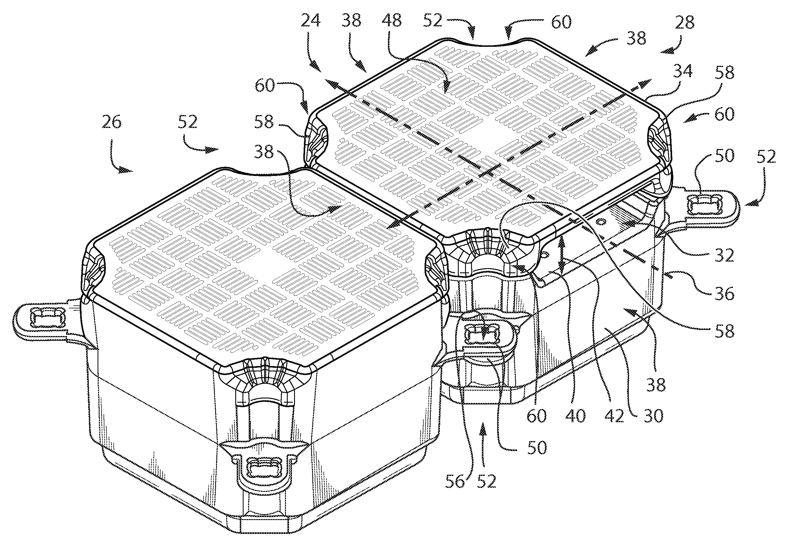
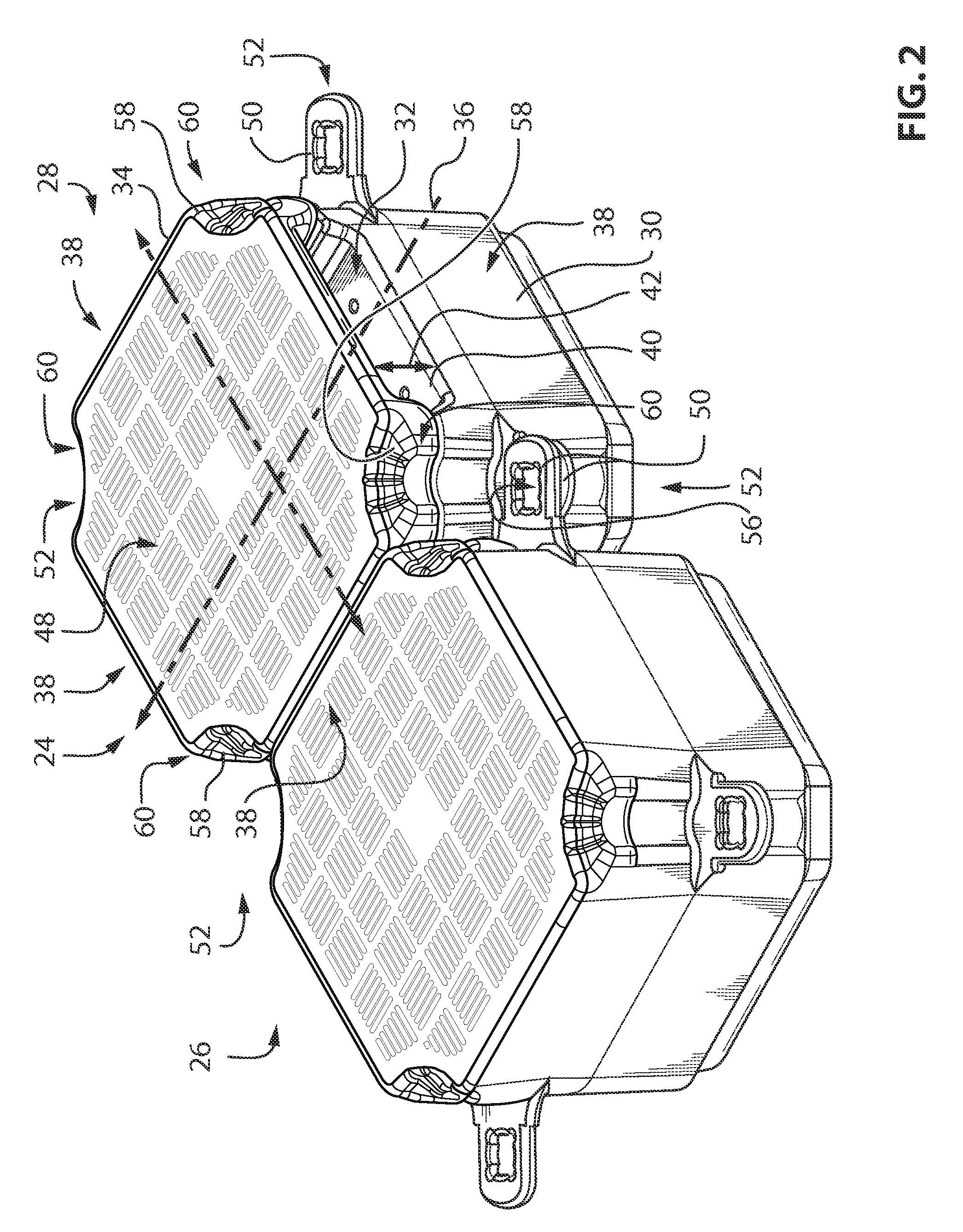
[0030]Now referring to FIG. 2, there is shown a dock unit 24 according to an embodiment of the invention, adjacent to a single piece dock unit 26. The dock unit 24 is attachable to the single piece dock unit 26 through one or more attachments 50 using a fastener, not shown, for forming a floating dock 28 having a flat floor. Note that the dock unit 24 may similarly be attached to another dock unit 24.

[0031]The dock unit 24 c...


PUM

PropertyMeasurementUnit
symmetry axisaaaaaaaaaa
translucentaaaaaaaaaa
distanceaaaaaaaaaa

Abstract

The present document describes a dock unit attachable to another dock unit with a fastener for forming a floating dock. The dock unit comprises a floating body having a mating surface and an attachment adapted to receive the fastener. Thereby attaching the floating body is able to be attached to the other dock unit. The dock unit further comprises a cover for covering the mating surface, the cover having a contact surface adapted to contact the fastener. In use, the contact surface is positioned proximate the attachment so that, when the attachment receives the fastener, the contact surface is contacted by the fastener, thereby limiting the movement of the cover with respect to the floating body.

Description

TECHNICAL FIELD[0001]This description relates to the field of floating docks. More particularly, this description relates to floating docks and to dock units for making such.BACKGROUND OF THE INVENTION[0002]Floating docks made from an assembly of similar dock units are well known. Each dock unit is typically made of a floating body, sometimes topped by a cover providing a walking surface. A passage between the cover and the floating body for different networks of cables or piping (i.e., under the floor of such floating docks) may be provided. Because the cover provides the walking surface, it is very important that it be securely attached to the floating body so that it does not shift position or rock when being walked upon, which could cause serious injuries to the person walking on the dock. Also, the attachments have to withstand efforts generated by accessories fixed to the cover, such as a base for delivering water or electricity, a mooring device, a fishing rod support, or a b...

Claims


Application Information

Patent Timeline
Patent Type & Authority Applications(United States)
IPC IPC(8): B63B35/44
CPCB63B3/08B63B3/48B63B5/00B63B5/06E02B3/064B63B35/58B63B2221/08B63B2241/16B63B5/24B63B35/38B63C1/02B63B73/49
Inventor LA VIOLETTE, M. ERICLAMOUREUX, M. SERGELAMOUREUX, M. ALEXANDRE
Owner CANDOCK
Why Eureka
Try Eureka