
Touch Screen Detecting Method and Apparatus

Inactive Publication Date: 2010-12-02
VIMICRO CORP
View PDF3 Cites 26 Cited by
  • Summary
  • Abstract
  • Description
  • Claims
  • Application Information

AI Technical Summary

Benefits of technology

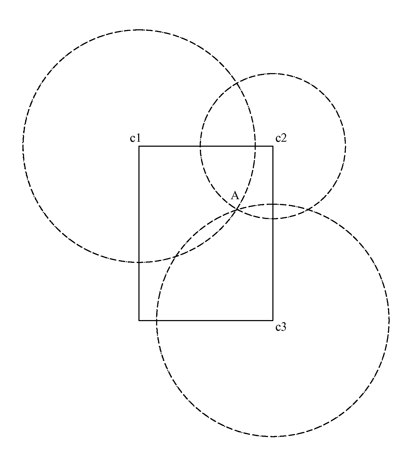
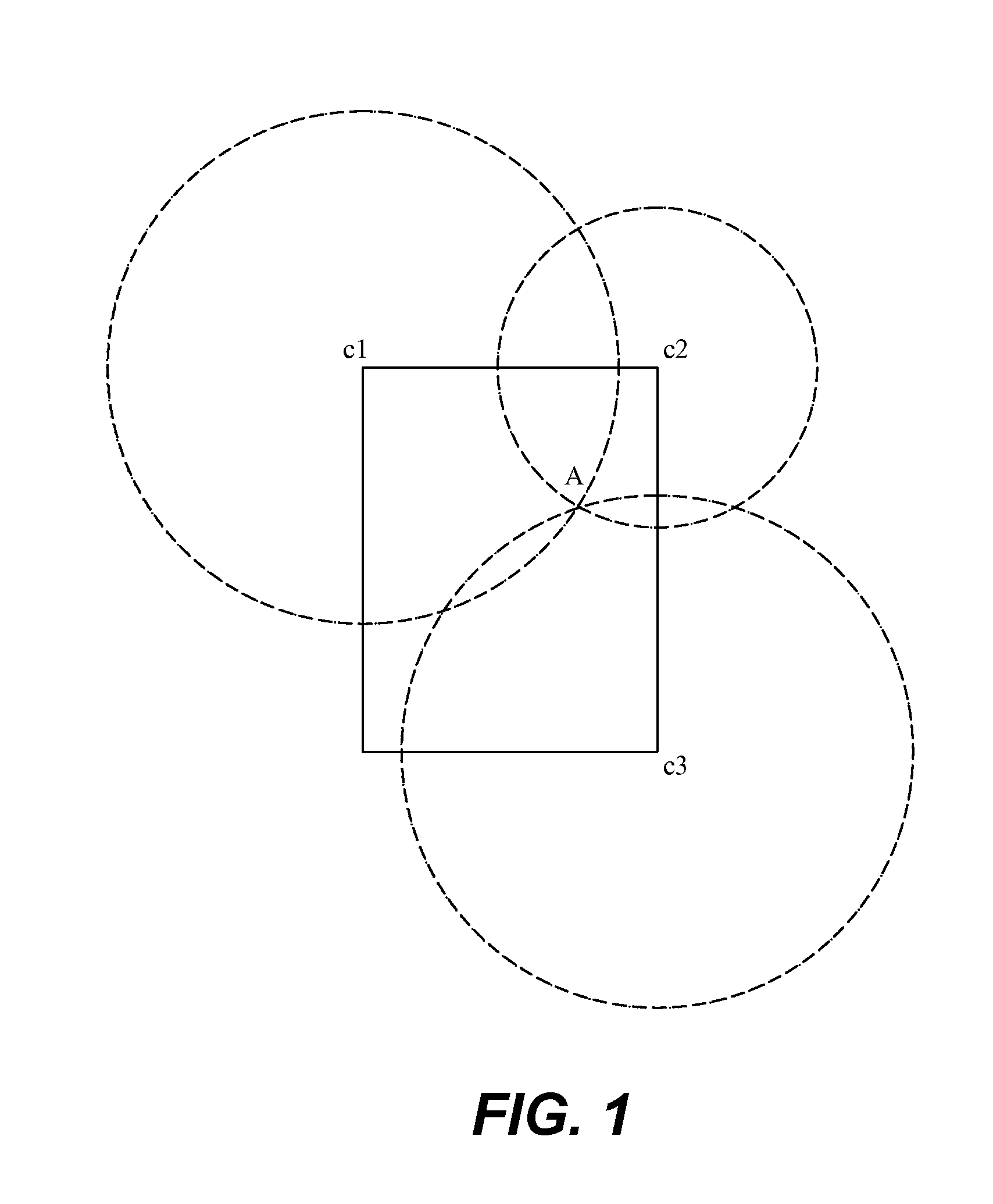
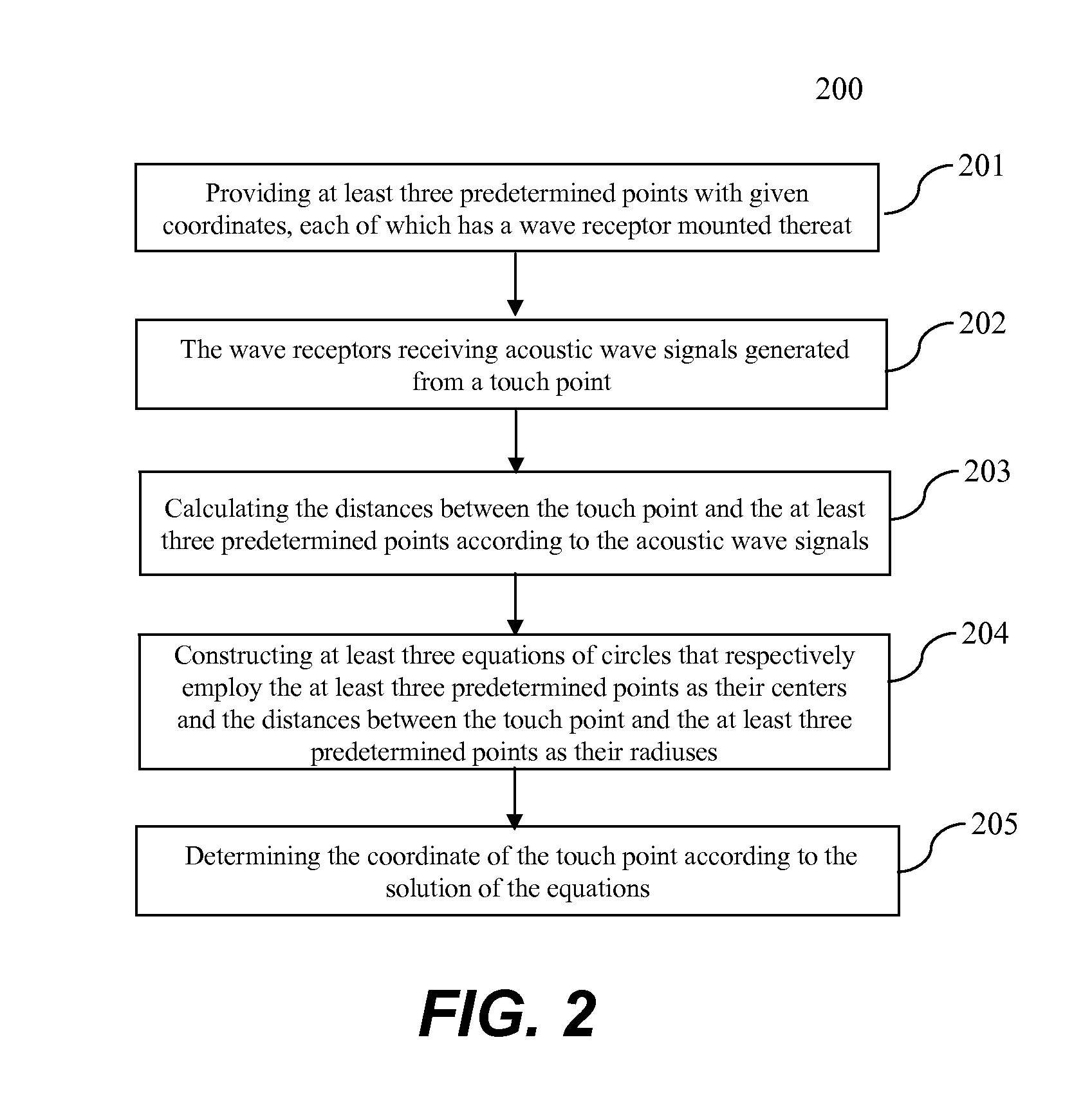
[0010]In general, the present invention is related to detecting one or more touches on a touch screen. According to one aspect of the present invention, at least three predetermined points are provided, where each of the at least three predetermined points has a wave receptor mounted thereat. When a touch to the touch screen happens, acoustic wave signals generated at the touch point are received by the wave receptors. The distances between the touch point and the three predetermined points are calculated according to the acoustic wave signals. At least three equations of circles are constructed to respectively employ the three predetermined points as their centers, the distances between the touch point and the at least three predetermined points as their radiuses. The coordinates of the touch point according to a common solution of the at least three equations are then determined. The same approach can be similarly applied to determining multiple touches on a touch screen.

Problems solved by technology

Thus, the conventional touch panels cannot detect multi-point contacts.

Method used


Image

  • Touch Screen Detecting Method and Apparatus
  • Touch Screen Detecting Method and Apparatus
  • Touch Screen Detecting Method and Apparatus

Examples


first embodiment

[0025]FIG. 2 shows a flowchart or process 200 showing a first touch detecting method according to the present invention. The process 200 may be implemented in software, hardware or a combination of both. In one embodiment, a module implementing the process 200 is stored in memory and executed in a processor.

[0026]At 201, at least three predetermined points are provided with given coordinates, each of points has a wave receptor mounted thereat. The at least three predetermined points may be defined on or around a touch panel. The at least three predetermined points include predetermined points c1, c2, and c3, which are not along a same straight line. In one embodiment, the predetermined points c1, c2, and c3 are advantageously defined at three corner points of the touch panel. FIG. 3 shows a touch panel 100 having three wave receptors S1, S2, and S3 which are respectively mounted at the predetermined points c1, c2, and c3. Distances between a touch point A and the predetermined point...

second embodiment

[0034]FIG. 4 shows a flowchart or process 400 showing a second touch detecting method according to the present invention. The process 400 may be implemented in software, hardware or a combination of both. In one embodiment, a module implementing the process 400 is stored in memory and executed in a processor. FIG. 5 illustrates a touch panel with three circles resulting from three points at three corners of the touch panel.

[0035]At 401, multiple touches simultaneously happen at a number of touch points on a touch panel. For example, FIG. 5 shows that point A and point B of the touch panel 100 are being touched at the same time. At 402, acoustic waves generated at the touch points respectively propagate in all directions, extending to the boundaries of the touch panel 100.

[0036]At 403, wave receptors disposed at three predetermined points receive the acoustic waves and detect the times the acoustic waves reach the wave receptors, respectively. The three predetermined points herein ma...


PUM


Abstract

Techniques for detecting one or more touches on a touch screen are disclosed. According to one aspect of the present invention, at least three predetermined points are provided, where each of the at least three predetermined points has a wave receptor mounted thereat. When a touch to the touch screen happens, acoustic wave signals generated at the touch point are received by the wave receptors. The distances between the touch point and the three predetermined points are calculated according to the acoustic wave signals. At least three equations of circles are constructed to respectively employ the three predetermined points as their centers, the distances between the touch point and the at least three predetermined points as their radiuses. The coordinates of the touch point according to a common solution of the at least three equations are then determined. The same approach can be similarly applied to determining multiple touches on a touch screen.

Description

BACKGROUND OF THE INVENTION[0001]1. Field of the Invention[0002]The present invention is related to touch screen detection techniques, more particularly to method and apparatus for detecting touches on a touch screen using an acoustic wave.[0003]2. Description of Related Art[0004]Touch screens are becoming main interface to input or receive information as human-machine interaction. A touch screen is an electronic visual display that can detect the presence and location of a touch within the display area. The term generally refers to touching the display of the device with a finger or hand. A touch detecting means is mounted on the top of a display screen and configured for detecting positions of touch events, receiving touch signals, and then transferring the touch signals to the control device. The control device is mainly configured for receiving the touch signals, converting the touch signals into coordinate positions of the touch events, and then transferring the coordinate posi...

Claims


Application Information

Patent Timeline
IPC IPC(8): G06F3/043
CPCG06F3/0416G06F3/043G06F3/04166
Inventor HUANG, BIN
Owner VIMICRO CORP
Learn More