Single frequency low power RFID device

a low-power, single-frequency technology, applied in the field of radio frequency identification (rfid) technology, can solve the problems of difficulty in determining which box was which, the current rfid system suffers from various problems, and the rfid reader suffers from high costs associated with programmable frequency synthesizers, power amplifiers, and high-speed high-resolution digitizers. achieve the effect of compact reader design and enhance short-range reads of tags

Active Publication Date: 2007-09-27
SYMBOL TECH LLC
View PDF10 Cites 173 Cited by
  • Summary
  • Abstract
  • Description
  • Claims
  • Application Information

AI Technical Summary

Benefits of technology

[0012]Methods, systems, and apparatuses for improved RFID readers are described herein. In an aspect, a SAW oscillator is used to provide high frequency oscillating signals for a reader, enabling a very compact reader design. In another aspect, a near field antenna is used in a reader to enhance short range reads of tags that are relatively free of tags. In a still further aspect, a reader circuit is mounted on a flexible substrate, to enable positioning of the reader circuit in a variety of locations.

Problems solved by technology

Current RFID systems suffer from various problems.
For example, RFID readers suffer from high costs associated with programmable frequency synthesizers, power amplifiers, and high-speed high-resolution digitizers.
Furthermore, if two or more tags and their associated boxes are present within the interrogation space, readers have difficulty distinguishing one tag from another within that interrogation space For example, if two boxes and their associated tags were present, the interrogator would read the presence of both tags, but specifically determining which box was which is difficult unless one of the boxes is removed to be singulated.
Readers require relatively large amounts of power to operate, which tends to limit battery life of mobile RFID terminals.
Furthermore, readers produce excessive heat when housed in confined spaces such as mobile terminals.
Still further, mobile RFID systems require large, bulky antennas to perform far field reads, to enable interrogation at long ranges.
RFID readers and tags are normally very susceptible to interference from other RFID readers in the general area.
For example, reader transmissions normally interfere with other readers in the nearby general area.
Readers transmitting at full power can even adversely affect the host system by which they are controlled and in which they are housed.

Method used


Image

  • Single frequency low power RFID device
  • Single frequency low power RFID device
  • Single frequency low power RFID device

Examples


example embodiments

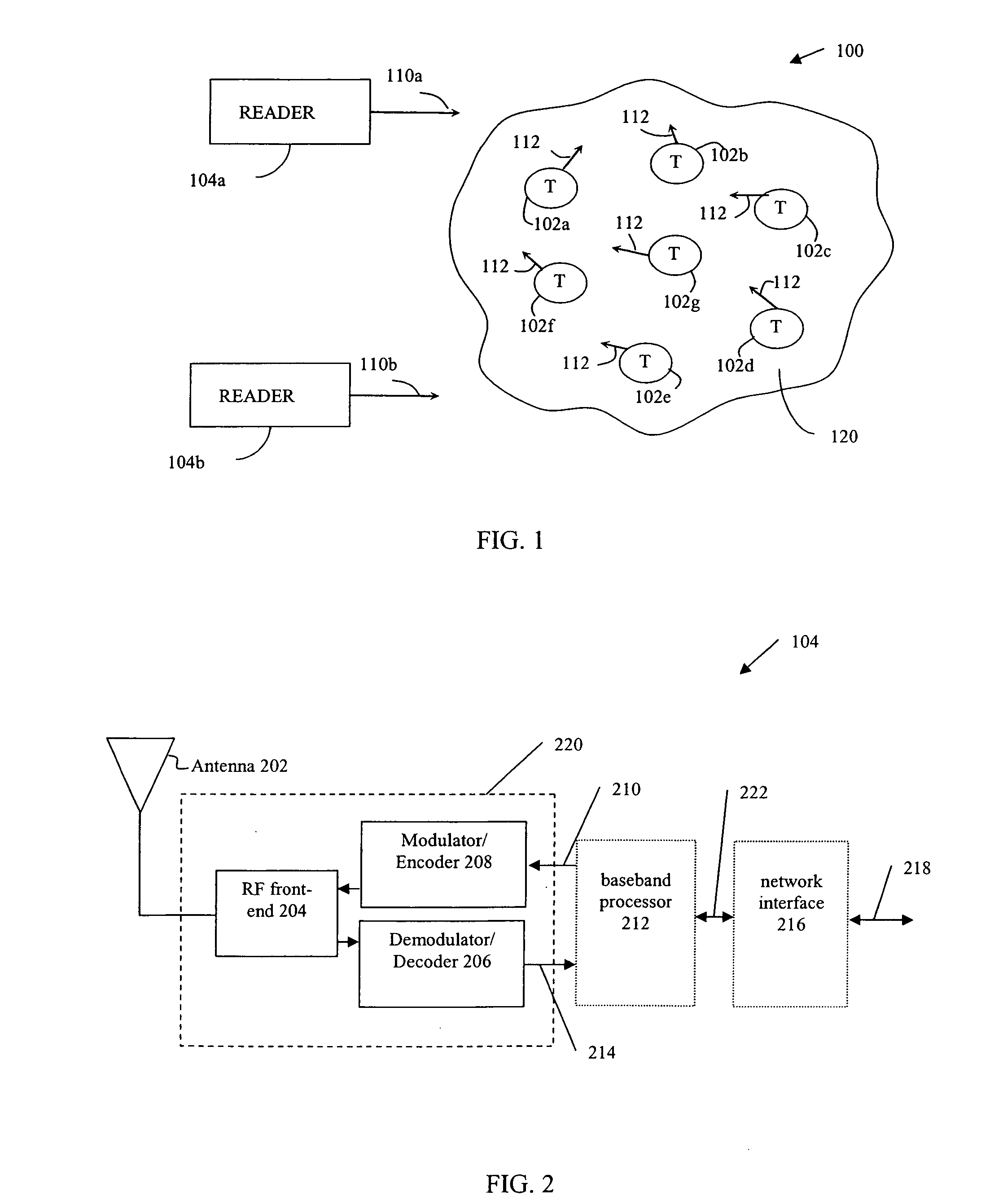
[0073]Embodiments are described herein for improved readers. These embodiments can be implemented anywhere that readers and tags are used. For example, embodiments can be implemented in a commercial or industrial environment, such as in a warehouse, a factory, a business, or store, and in a military or other non-commercial environment.

[0074]In embodiment, transceivers are described that are suitable for RFID reader devices. The transceivers are very compact, and thus can be fit into small form factors. For example, in one embodiment, a transceiver is incorporated into a RFID module that is an attachable accessory for a host computer, such as a mobile handheld computer.

[0075]In embodiments, various types of oscillators can be used to generate a carrier frequency for the transceiver. In example transceivers described below, a surface acoustic wave (SAW) device is described as generating a carrier frequency for a transceiver, and in some embodiments also performs a modulating function....

example system embodiments

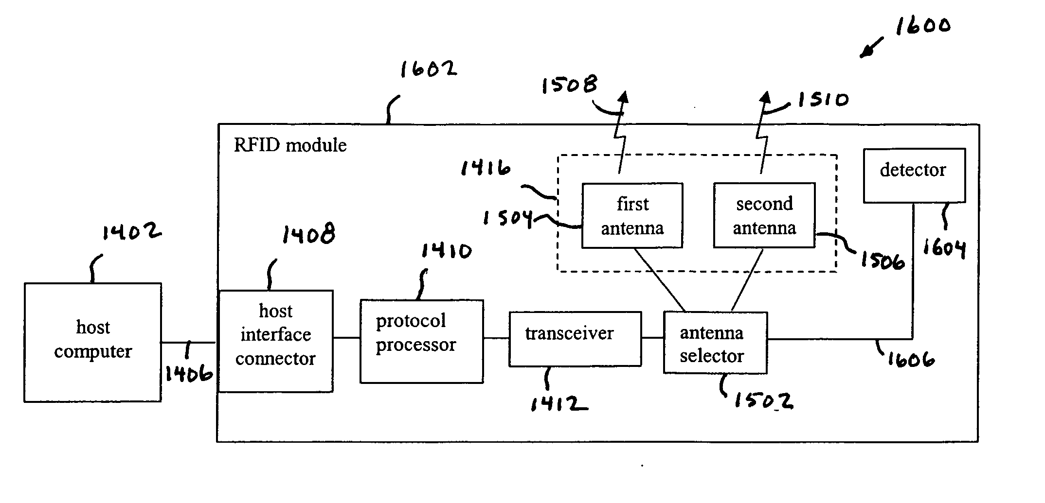
[0139]As described above, embodiments of the present invention can be implemented in many forms, including in RFID readers, in attachable RFID module accessories, in barcode readers, in mobile devices, and in other devices. Some further example system implementations are described below. These embodiments may be adapted, modified, and combined in any manner, as would be apparent to persons skilled in the relevant art(s).

[0140]For instance, FIG. 14 shows a RFID communication system 1400, according to an example embodiment of the present invention. As shown in FIG. 14, system 1400 includes a host computer 1402 and a RFID module 1404. RFID module 1404 includes RFID functionality for communicating with RFID tags. RFID module 1404 may be implemented in a reader, in an RFID module, or other device. Host computer 1402 may be computer system, similar to host 1002 described above. Host computer 1402 may be implemented in a desktop computer, server, mobile handheld computer (e.g., a PDA), a b...

embodiments

Example Advantages of Embodiments

[0160]Numerous advantages are provided by embodiments of the present invention, some of which were described above. Example advantages are described as follows that may or may not have been described above. For example, embodiments have a small size that is easy to integrate into mobile terminals. For example, ASIC and SAW devices can be integrated into a laser scanner engine. Furthermore, the reader circuits can make use of existing laser scanner ASICs, such as being incorporated into the same ASIC, or interfaced with the scanner ASIC in a convenient manner. The reader transceiver circuits use very low power. For example, the power used is approximately the same as used by a laser scanner. The reader embodiments are very light weight. Embodiments can be integrated into a SANDISK™ (SD) format card to upgrade numerous existing products and devices that are compatible with SD cards. Furthermore, due to reduced interference, embodiments allow more RFID ...


PUM


Abstract

Methods, systems, and apparatuses for a reader transceiver circuit are described. The reader transceiver circuit incorporates a frequency generator, such as a surface acoustic wave (SAW) oscillator. A reader incorporating the reader transceiver circuit is configured to read a tag at very close range, including while being in contact with the tag. The transceiver can be coupled to various host devices in a variety of ways, including being located in a RFID reader (e.g., mobile or fixed position), a computing device, a barcode reader, etc. The transceiver can be located in an RFID module that is attachable to a host device, can be configured in the host device, or can be configured to communicate with the host device over a distance. The RFID module may include one or more antennas, such as a first antenna configured to receive a magnetic field component of an electromagnetic wave and a second antenna configured to receive an electric field component of an electromagnetic wave. The RFID module may include a detector that is configured to determine if the RFID module is positioned in proximity to an object, such as a RFID tag. The detector may operate as a trigger for the RFID module, to enable or trigger a function of the RFID module.

Description

[0001]The present application claims the benefit of U.S. Appl. No. 60 / 784,450, filed Mar. 22, 2006, which is incorporated by reference herein in its entirety.BACKGROUND OF THE INVENTION[0002]1. Field of the Invention[0003]The invention relates to radio frequency identification (RFID) technology, and in particular, to improved RFID readers.[0004]2. Background Art[0005]Radio frequency identification (RFID) tags are electronic devices that may be affixed to items whose presence is to be detected and / or monitored. The presence of an RFID tag, and therefore the presence of the item to which the tag is affixed, may be checked and monitored wirelessly by devices known as “readers.” Readers typically have one or more antennas transmitting radio frequency signals to which tags respond. Because the reader “interrogates” RFID tags, and receives signals back from the tags in response to the interrogation, the reader is sometimes termed as “reader interrogator” or simply “interrogator.”[0006]Wit...

Claims


Application Information

Patent Timeline
Patent Type & Authority Applications(United States)
IPC IPC(8): G08B13/14
CPCG06K7/0008
Inventor DURON, MARKGIEBEL, JAMESGOREN, DAVIDWULFF, THOMASKNADLE, RICHARD T.BROCK, CHRISTOPHER
Owner SYMBOL TECH LLC
Why Eureka
Try Eureka