Method and apparatus for generating high output power gas discharge based source of extreme ultraviolet radiation and/or soft x-rays

Inactive Publication Date: 2002-11-14
USHIO DENKI KK
View PDF88 Cites 179 Cited by
  • Summary
  • Abstract
  • Description
  • Claims
  • Application Information

AI Technical Summary

Benefits of technology

[0064] A set of baffles 400 is preferably provided after the clipping aperture. The baffles 400 may be configured similar to those described at U.S. Pat. No. 5,027,366, which is hereby incorporated by reference, or otherwise as understood by those skilled in the art. The baffles 400 serve to diffuse the effect of acoustic waves emanating from the pinch region such as the flow of gases and contaminant particulates traveling with the acoustic waves, as well as to prevent reflections back into the pinch region. The baffles 400 preferably absorb such disturbances.
[0066] The UV light from the ionizer unit 500 ionizes dust particles that tend to travel along with the beam. An electrostatic particle filter 600a, 600b is provided for collecting the charged dust particles resulting in a cleaner beam path. Fewer of these contaminants are deposited on the window 18 and elsewhere in the chamber 14. Also, the ionizer, precipitator arrangement reduces reflections from the particulates by the EUV beam, as well as other disturbances to the beam.
[0067] In accordance with preferred embodiments, the EUV source schematically illustrated at FIG. 1 and described above exhibits output emission characteristics advantageously suitable for industrial applications, and particularly having output emission characteristics more suitable for photolithographic, mask writing and mask and wafer inspection applications. The clipping aperture 300 and / or set of baffles 400 reduce the influence of acoustic waves emanating from the pinch region 12. The clipping aperture 300 also matches and / or defines the divergence of the beam. The prepulse generated prior to the main pulse serves to homogenize the plasma shell to reduce the probability that arcing will degrade the pinch symmetry and the resulting EUV beam and that hotspots due to the arcing will deteriorate the electrodes 30, 32. The ionizer 500 and precipitator 600a, 600b serve to remove particulates from the beam path preventing adverse effects on the beam and components such as the beam exit window 18 of the chamber 10 where the particulates may become otherwise deposited.
[0085] Among many choices of contour, a flat mirror 710 will improve the output power of the source only slightly, but may be useful in conjunction with another mirror on one or more sides of the plasma column and / or when the plasma is significantly blocking the beam path to the opening and / or aperture 300, with the advantage of ease of manufacture. An elliptical or spherical mirror with adapted focal length may be used to focus the radiation in front of or just passed the output opening and / or aperture 300, and can be advantageous for application processing proximate to the EUV source and / or using additional imaging or beam shaping optics, e.g., a reflective imaging system for photolithographic reduction. A hyperbolically-shaped mirror may be used to generate almost parallel radiation or a collimated beam, such as when it is desired that the beam travel a significant distance prior to being re-directed or shaped with additional EUV optics or for direct application to a workpiece, or when a performance of an imaging system can be enhanced by using collimated input radiation and / or when collimated radiation produces the highest beam transport efficiency (note that the beam path may be preferably enclosed and the atmosphere prepared to be free of contaminants and / or photoabsorbing species of the EUV radiation, e.g., by evacuation and / or purging with inert gas; see U.S. Pat. Nos. 6,327,290, 6,219,368, 6,345,065, 6,219,368, 5,559,584, 5,221,823, 5,763,855, 5,811,753 and 4,616,908, and U.S. patent applications Ser. Nos. 09 / 598,552, 09 / 712,877, 09 / 727,600 and 09 / 131,580, which applications are assigned to the same assignee as the present application, and all of these patents and patent applications are hereby incorporated by reference). One can generally use this degree of freedom of changing the mirror shape, contour, degree of curvature, etc., to adapt the emission properties of the EUV source to the optical system of the application.
[0087] As shown in Table A, the highest increase of the output power due to the presence of mirrors 710, 730 is expected for the Z-pinch and HCT-pinch geometries, and is 230% and 70%, respectively. The usable angles of capillary discharges and plasmafocus devices initially are very high such that the expected improvement due to the presence of the mirrors 750, 770 is smaller in relation to the output power. However, the collimating or focusing property of the mirrors 750, 770 can yield greater improvement in the quality of the output beam for the capillary discharge and plasma focus systems than appears from these calculations (and the same may be true for the Z-pinch and HCT-pinch devices).1TABLE A Source / Capillary Parameter z-pinch HCT-pinch discharge plasmafocus Solid angle 0.3 sr 1 sr .pi.sr 2.pi.sr Output 0.3 / 4.pi. I.sub.0 1 / 4.pi. I.sub.0 .pi. / 4.pi. I.sub.0 2.pi. / 4.pi. I.sub.0 Estimated 1 sr 1 sr 0.3 sr 1 sr Mirror acceptance angle Multilayer 70% 70% 70% 70% reflectivity Increase of 1 / 4.pi. .times. 0.7 I.sub.0 1 / 4.pi. .times. 0.7 I.sub.0 0.3 / 4.pi. .times. 0.7 I.sub.0 1 / 4.pi. .times. 0.7 I.sub.0 output by mirror Increase of 5.6% 5.6% 1.7% 5.6% output in % of I.sub.0 Expected 230% 70% 6.8% 11.2% improvement
[0088] The preferred mirrors 710, 730, 750, 770 become treated by heat and ion bombardment from the plasma. These can tend to shorten the lifetimes of the mirrors 710, 730, 750, 770. Therefore, special heat resistant kinds of multilayer systems are preferred for use with the EUV sources described herein. In particular, preferred mirrors 710, 730, 750, 770 may be formed from combinations of Mo.sub.2C--Si or Mo--Si--Mo.sub.2C, or other such structures that may be understood and / or later achieved by those skilled in the art as being particularly heat and / or other damage resistant and having a long lifetime, while still providing substantial reflectivity (e.g., 50% or more, and preferably 70% or more).

Problems solved by technology

The rapid collapse of the shell results in collisions between all portions of the incoming shell at the central axis with radially opposed portions of the incoming shell.

Method used


Image

  • Method and apparatus for generating high output power gas discharge based source of extreme ultraviolet radiation and/or soft x-rays
  • Method and apparatus for generating high output power gas discharge based source of extreme ultraviolet radiation and/or soft x-rays
  • Method and apparatus for generating high output power gas discharge based source of extreme ultraviolet radiation and/or soft x-rays

Examples


sixth embodiment

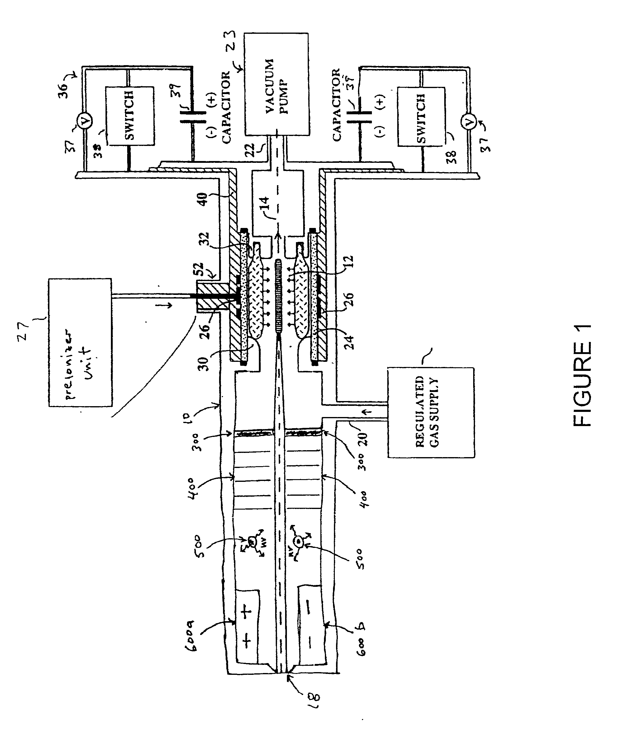
[0069] FIG. 2 schematically illustrates an EUV generating source, and particularly a Z-pinch device, including a reflecting surface opposite a beam output side of the central axis according to a The EUV source schematically shown at FIG. 2 includes an anode 702 and a cathode 704 electrically separated by an insulator 706. The exemplary and illustrative Z-pinch device shown at FIG. 2 also includes a clipping aperture 708 for matching and / or defining a divergence for the EUV beam. The clipping aperture 708 may include one or more features of the aperture 300 of FIG. 1. Although not shown at FIG. 2, the Z-pinch device may also include any of baffles 400, ionizer 500 and precipitator 600a, 600b described with reference to the system shown at FIG. 1, e.g., after the clipping aperture 708, 300 along the EUV beam path. The EUV source of FIG. 2 further includes an EUV mirror 710 or EUV reflecting surface 710.

[0070] In operation, the Z-pinch EUV source of FIG. 2 rapidly generates a dense pl...

seventh embodiment

[0072] FIG. 3 schematically illustrates an EUV generating source, and particularly a hollow cathode triggered (HCT) pinch device, including a reflecting surface opposite a beam output side of the central axis according to a The exemplary and illustrative HCT-pinch EUV source schematically shown at FIG. 3 includes an anode 722 and a hollow cathode 724 electrically separated by an insulator 726. Although not shown at FIG. 3, the HCT-pinch device may also include any of clipping aperture 300, baffles 400, ionizer 500 and precipitator 600a, 600b described with reference to FIG. 1. The EUV source of FIG. 3 further includes an EUV mirror 730 or EUV reflecting surface 730.

[0073] In operation, the HCT-pinch EUV source of FIG. 3 rapidly generates a dense plasma 732, when a potential difference is applied to the electrodes 722, 724. EUV radiation 714 emanates from the dense plasma 732 particularly in each of the two opposing, axial directions (i.e., to the top and to the bottom of the page i...

eighth embodiment

[0075] FIG. 4 schematically illustrates an EUV generating source, and particularly a capillary discharge (CD) device, including a reflecting surface opposite a beam output side of the central axis according to a The exemplary and illustrative capillary discharge EUV source schematically shown at FIG. 4 includes an anode 742 and a cathode 744 electrically separated by an insulator 746 including a capillary 747 within which a plasma 752 is created. The capillary discharge device shown at FIG. 4 also includes a clipping aperture 748 for matching and / or defining a divergence for the EUV beam. The clipping aperture 748 may include one or more features of the aperture 300 of FIG. 1 and / or the aperture 708 of FIG. 2. The gases used to form the plasma 752 of the device of FIG. 4, as well as for the devices of FIGS. 1 and 3-5, or another device in accordance with a preferred embodiment, may be supplied through gas supply 758, as shown, or otherwise as understood by those skilled in the art....


PUM

PropertyMeasurementUnit
at-wavelength aaaaaaaaaa
reflectivityaaaaaaaaaa

Abstract

An EUV photon source includes a plasma chamber filled with a gas mixture, multiple electrodes within the plasma chamber defining a plasma region and a central axis, a power supply circuit connected to the electrodes for delivering a main pulse to the electrodes for energizing the plasma around the central axis to produce an EUV beam output along the central axis, and a preionizer for ionizing the gas mixture in preparing to form a dense plasma around the central axis upon application of the main pulse from the power supply circuit to the electrodes. The EUV source preferably includes an ionizing unit and precipitator for collecting contaminant particulates from the output beam path. A set of baffles may be disposed along the beam path outside of the pinch region to diffuse gaseous and contaminant particulate flow emanating from the pinch region and to absorb or reflect acoustic waves emanating from the pinch region away from the pinch region. A clipping aperture, preferably formed of ceramic and / or Al2O3, for at least partially defining an acceptance angle of the EUV beam. The power supply circuit may generates the main pulse and a relatively low energy prepulse for homogenizing the preionized plasma prior to the main pulse. A multi-layer EUV mirror is preferably disposed opposite a beam output side of the pinch region for reflecting radiation along the central axis for output along the beam path of the EUV beam. The EUV mirror preferably has a curved contour for substantially collimating or focusing the reflected radiation. In particular, the EUV mirror may preferably have a hyperbolic contour.

Description

PRIORITY[0001] This application claims the benefit of priority to U.S. provisional patent application No. 60 / 281,446, filed Apr. 3, 2001.[0002] 1. Field of the Invention[0003] The present invention relates to extreme ultraviolet (EUV) lithography, and particularly to an EUV radiation source configured for transmitting an improved EUV beam.[0004] 2. Discussion of the Related Art[0005] Semiconductor manufacturers are currently using deep ultraviolet (DUV) lithography tools based on KrF-excimer laser systems operating around 248 nm, as well as the following generation of ArF-excimer laser systems operating around 193 nm. Industrial applications in the Vacuum UV (VUV) range involve the use of the F.sub.2-laser operating around 157 nm. EUV radiation sources for EUV lithography emitting 11-15 nm photon beams are currently being developed.[0006] EUV radiation sources have an advantageous output emission beam including 11-15 nm wavelength photons having photon energies greater than 90 eV. T...

Claims


Application Information

Patent Timeline
Patent Type & Authority Applications(United States)
IPC IPC(8): B03C3/38G03F7/20H05G2/00
CPCB03C3/383B82Y10/00H05G2/003G03F7/70175G03F7/70916G03F7/70033
Inventor SCHRIEVER, GUIDOREBHAN, ULRICH
Owner USHIO DENKI KK
Why Eureka
Try Eureka