Tracking system calibration using object position and orientation

a technology of tracking system and object position, applied in the direction of television system, direction/deviation determining electromagnetic system, instruments, etc., can solve the problem that conventional gaming system cannot perform calibration without such a controlled and precise process

Active Publication Date: 2010-12-02
SONY COMPUTER ENTERTAINMENT INC
View PDF54 Cites 128 Cited by
  • Summary
  • Abstract
  • Description
  • Claims
  • Application Information

AI Technical Summary

Problems solved by technology

Conventional gaming systems are not able to perform calibration without such a controlled and precise process.

Method used


Image

  • Tracking system calibration using object position and orientation
  • Tracking system calibration using object position and orientation
  • Tracking system calibration using object position and orientation

Examples


Embodiment Construction

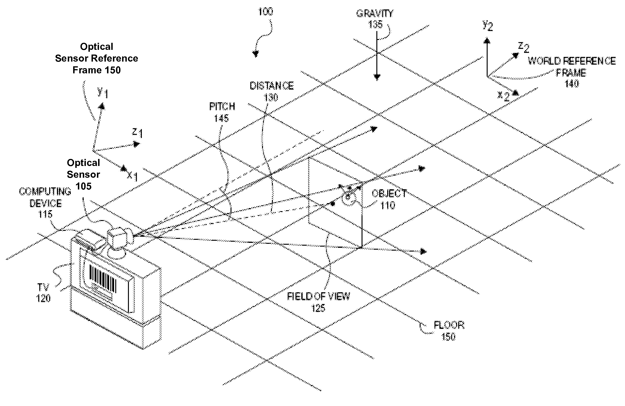
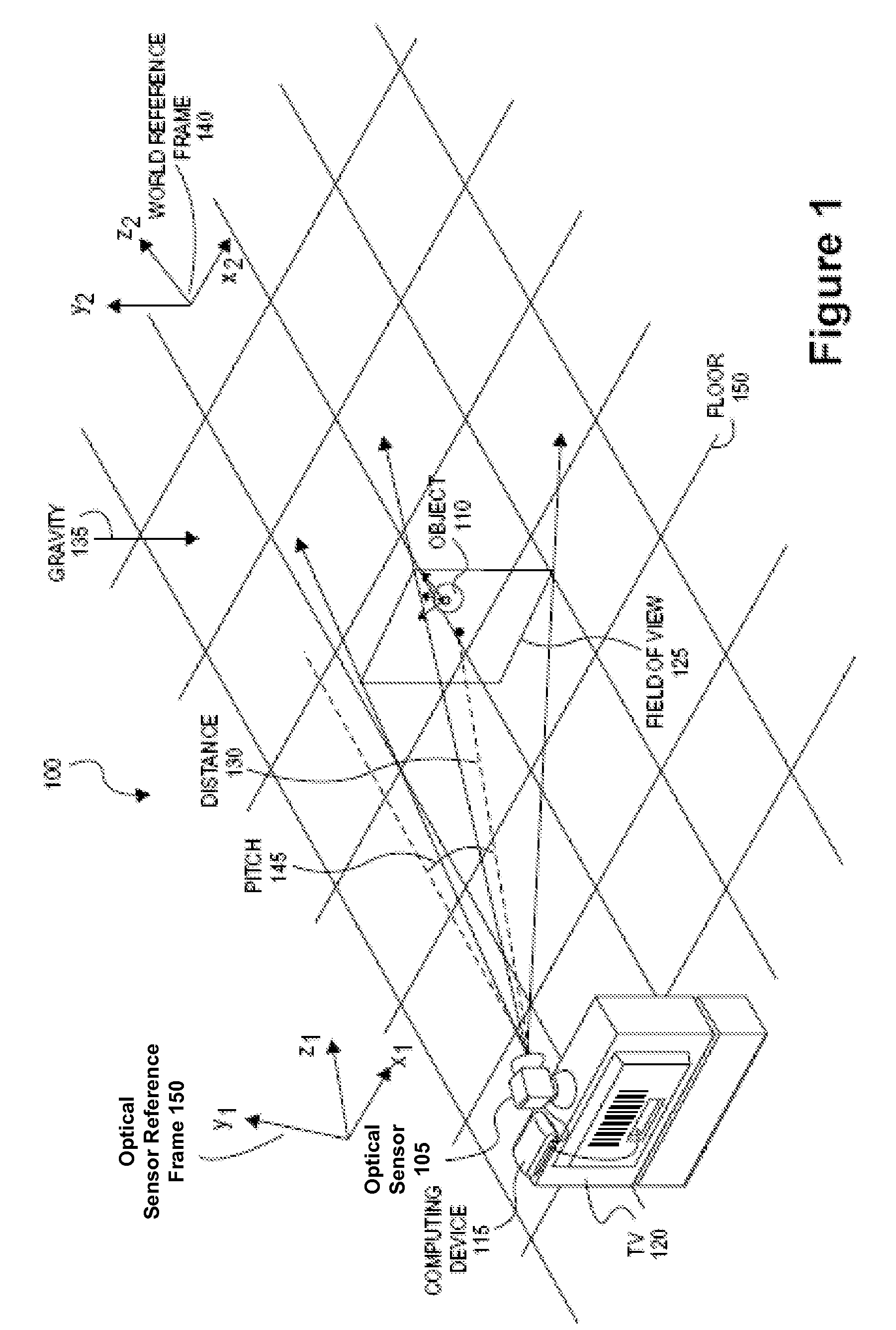
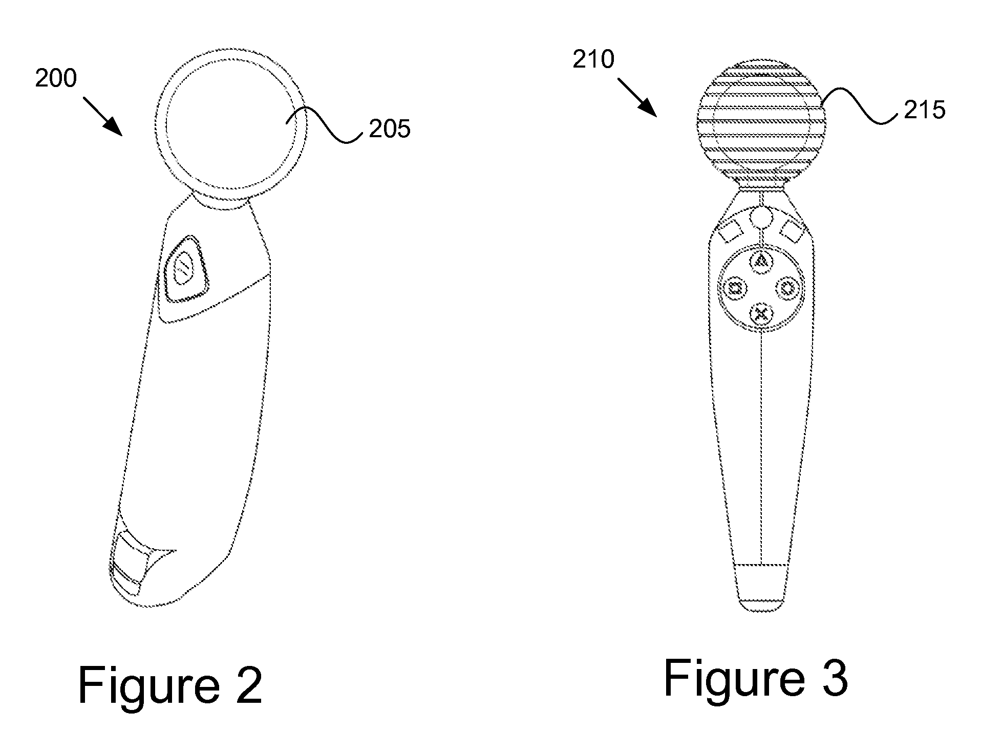
[0017]Described herein is a method and apparatus for calibrating a tracking system for use in a gaming system. In one embodiment, a user can calibrate the tracking system simply by pointing an object (e.g., a game controller) at an optical sensor of the tracking system, and pressing a button. In one embodiment, to calibrate the tracking system, positional data (e.g., image locations and image sizes) of a tracked object are received by an optical sensor as the object is pointed approximately toward the optical sensor. The optical sensor sends the positional data to a computing device (e.g., to a video game console). The computing device computes a first angle of the object with respect to an optical axis of the optical sensor using the received positional data. The computing device receives inertial data corresponding to the object, wherein a second angle of the object with respect to a plane normal to gravity can be computed from the inertial data. The computing device determines a ...


PUM


Abstract

To calibrate a tracking system, a computing device receives positional data of a tracked object from an optical sensor as the object is pointed approximately toward the optical sensor. The computing device computes a first angle of the object with respect to an optical axis of the optical sensor using the received positional data. The computing device receives inertial data corresponding to the object, wherein a second angle of the object with respect to a plane normal to gravity can be computed from the inertial data. The computing device determines a pitch of the optical sensor using the first angle and the second angle.

Description

RELATED APPLICATIONS[0001]This patent application claims the benefit under 35 U.S.C. §119(e) of U.S. Provisional Application No. 61 / 182,702, filed May 30, 2009, which is herein incorporated by reference. This application is related to co-pending U.S. patent application Ser. No. 12 / 435,386, entitled, “Tracking System Calibration With Minimal User Input”, filed on May 4, 2009 and co-pending U.S. patent application Ser. No. 12 / 435,285, entitled, “Correcting Angle Error In A Tracking System,” filed on May 4, 2009.FIELD OF THE INVENTION[0002]The present invention relates generally to calibrating a tracking system, and more particularly to calibrating a tracking system that is used to track the location of an object based on positional data of the object and additional received or known data pertaining to the object.DESCRIPTION OF THE RELATED ART[0003]A growing trend in the computer gaming industry is to develop games that increase the interaction between a user and a gaming system. One w...

Claims


Application Information

Patent Timeline
Patent Type & Authority Applications(United States)
IPC IPC(8): H04N5/225G06F3/033G06F3/0346
CPCG01S3/7803G01S3/784G06F3/0304G06F3/0346
Inventor MARKS, RICHARD LEELARSEN, ERIC
Owner SONY COMPUTER ENTERTAINMENT INC
Why Eureka
Try Eureka