
Graphical Indicator which Specifies Parallelization of Iterative Program Code in a Graphical Data Flow Program

Active Publication Date: 2010-12-02
NATIONAL INSTRUMENTS
View PDF14 Cites 41 Cited by
  • Summary
  • Abstract
  • Description
  • Claims
  • Application Information

AI Technical Summary

Benefits of technology

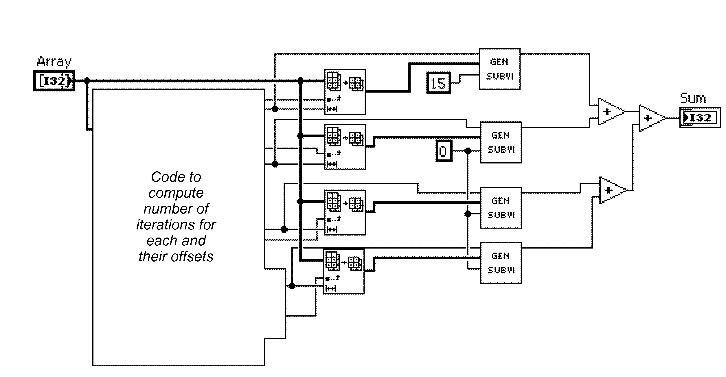
[0018]The method may further include executing the data flow program, including each of the second data flow program portions executing the respective one or more iterations, where the plurality of second data flow program portions collectively execute all iterations specified for the first data flow program portion.
[0019]Note that the program code implementing the plurality of second data flow program portions may be automati

Problems solved by technology

However, implementing such parallelism in current graphical programming systems requires that a user analyze the graphical program code, the execution target (multi-core / multi-processor), and the data to be processed, and manually customize the graphical program, e.g., writing or rewriting graphical program code, which may be difficult, tedious, and error prone.
There is no way to easily tune or test such transformations by hand.

Method used


Image

  • Graphical Indicator which Specifies Parallelization of Iterative Program Code in a Graphical Data Flow Program
  • Graphical Indicator which Specifies Parallelization of Iterative Program Code in a Graphical Data Flow Program
  • Graphical Indicator which Specifies Parallelization of Iterative Program Code in a Graphical Data Flow Program

Examples


Embodiment Construction

Incorporation by Reference

[0049]The following references are hereby incorporated by reference in their entirety as though fully and completely set forth herein:

[0050]U.S. Pat. No. 4,914,568 titled “Graphical System for Modeling a Process and Associated Method,” issued on Apr. 3, 1990.

[0051]U.S. Pat. No. 5,481,741 titled “Method and Apparatus for Providing Attribute Nodes in a Graphical Data Flow Environment”.

[0052]U.S. Pat. No. 6,173,438 titled “Embedded Graphical Programming System” filed Aug. 18, 1997.

[0053]U.S. Pat. No. 6,219,628 titled “System and Method for Configuring an Instrument to Perform Measurement Functions Utilizing Conversion of Graphical Programs into Hardware Implementations,” filed Aug. 18, 1997.

[0054]U.S. Patent Application Publication No. 20010020291 (Ser. No. 09 / 745,023) titled “System and Method for Programmatically Generating a Graphical Program in Response to Program Information,” filed Dec. 20, 2000.

Terms

[0055]The following is a glossary of terms used in the...


PUM


Abstract

System and method for automatically parallelizing iterative functionality in a data flow program. A data flow program is stored that includes a first data flow program portion, where the first data flow program portion is iterative. Program code implementing a plurality of second data flow program portions is automatically generated based on the first data flow program portion, where each of the second data flow program portions is configured to execute a respective one or more iterations. The plurality of second data flow program portions are configured to execute at least a portion of iterations concurrently during execution of the data flow program. Execution of the plurality of second data flow program portions is functionally equivalent to sequential execution of the iterations of the first data flow program portion.

Description

FIELD OF THE INVENTION[0001]The present invention relates to the field of data flow programming, and more particularly to automatically parallelizing iterative functionality in data flow programs.DESCRIPTION OF THE RELATED ART[0002]Data flow programming is a programming approach or protocol with many industrial (and other) applications. In data flow (or dataflow) programming, the program architecture is that of a directed graph specifying the flow of data through the program. In data flow programs functions execute whenever the necessary input data are available. Data flow programs can be contrasted with procedural programs, which specify an execution flow of computations to be performed.[0003]Graphical programming has also become a powerful tool available to programmers. Graphical programming environments such as the National Instruments LabVIEW product have become very popular. Tools such as LabVIEW have greatly increased the productivity of programmers, and increasing numbers of ...

Claims


Application Information

Patent Timeline
IPC IPC(8): G06F9/44G06F9/45
CPCG06F8/452G06F8/20G06F8/38G06F8/34G06F8/30
Inventor BORDELON, ADAM L.DYE, ROBERT E.YI, HAORANFLETCHER, MARY E.
Owner NATIONAL INSTRUMENTS
Learn More