
Gas-generating devices with grain-retention structures and related methods and systems

a technology of gas-generating devices and grain-retention structures, which is applied in the direction of explosives, pedestrian/occupant safety arrangements, dental surgery, etc., can solve the problems of large gas-generating grains that have an unpredictable burn rate and inconsistent gas production, large gas-generating grains that tend to develop cracks and other structural defects,

Active Publication Date: 2010-12-09
NORTHROP GRUMMAN INNOVATION SYST INC
View PDF70 Cites 16 Cited by
  • Summary
  • Abstract
  • Description
  • Claims
  • Application Information

AI Technical Summary

Benefits of technology

[0011]Additionally, embodiments of the present invention relate to fire suppression systems, and other applications requiring multiple grains in a larger gas generator, that comprise at least one combustion chamber, at least one effluent train coupled to each combustion chamber, and at least one gas-generating device located within each combustion chamber. Each gas-generating device may comprise a plurality of fire-suppressing gas-generant grains constrained to a longitudinally stacked configuration by a frame. One or more retention plates may be coupled to the frame, fixed relative to the frame, and positioned between at least some adjacent gas-generant grains of the plurality of fire-suppressing gas-generant grains.
[0012]In accordance with one embodiment of the present invention, a gas generator may be manufactured by arranging a plurality of gas-generant grains in a longitudinal stack. One or more retaining members may be positioned between at least one gas-generant grain and at least one adjacent gas-generant grain of the plurality of gas-generant grains in the longitudinal stack, and each retaining member may be fixed to the frame.
[0013]In accordance with another embodiment of the present invention, a gas may be generated by combusting a plurality of longitudinally stacked gas-generant grains to generate a gas. The lateral movement of at least some of the plurality of longitudinally stacked gas-generant grains may be restricted during combustion with a frame structure, and the longitudinal movement of the plurality of longitudinally stacked gas-generant grains may be restricted during combustion by maintaining at least one retaining member between adjacent gas-generant grains of the plurality of longitudinally stacked gas-generant grains and maintaining the one or more retaining members fixed relative to the frame during combustion.

Problems solved by technology

For example, as gas-generating grains are produced in a larger scale the reliability of the grains becomes an issue.
Specifically, larger gas-generating grains tend to have an unpredictable burn rate and have in inconsistent gas production throughout the burn, as well as having other undesirable burn characteristics.
Additionally, larger gas-generating grains tend to develop cracks and other structural defects that contribute to the unreliability of these larger grains and the undesirable burn characteristics of such larger grains.
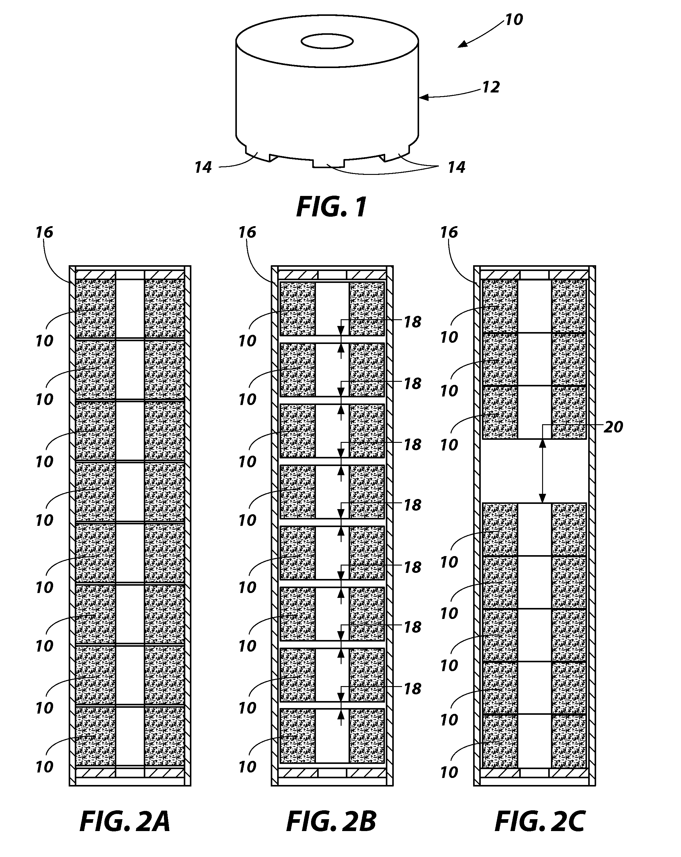
However, the inventors of the present invention discovered that the interaction between the smaller, burning gas-generating grains within the gas generator has undesirable effects on the gas generator performance.
The collisions at such higher velocities may be relatively energetic and may result in material of the grains 10, particularly spent material of the grains 10 or so called “clinkers,” breaking apart, which may result in the production of particulates.
This production of particles may be undesirable, as the gas-generating grains 10 may be enclosed within a combustion chamber of a gas-generating assembly (not shown), and as particulates are carried through the gas-generating assembly they may foul a filter of the assembly and reduce gas flow and / or may be carried out of the gas-generating assembly.
The particulates that may be carried out of the gas-generating assembly may be undesirable.
Additionally, excessive smoke and undesirable combustion products may result and may also be expelled from the gas-generating assembly.

Method used


Image

  • Gas-generating devices with grain-retention structures and related methods and systems
  • Gas-generating devices with grain-retention structures and related methods and systems
  • Gas-generating devices with grain-retention structures and related methods and systems

Examples


Embodiment Construction

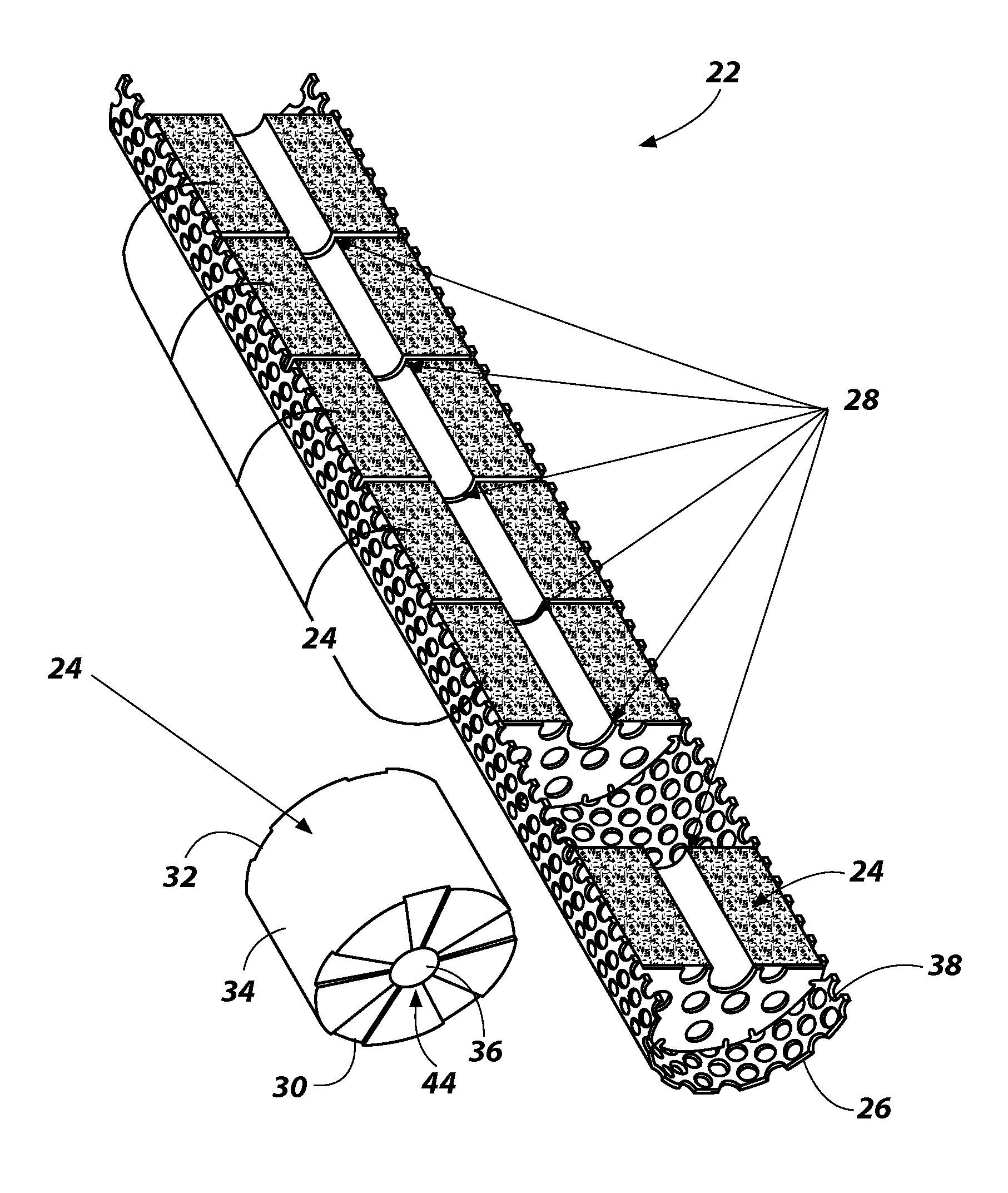
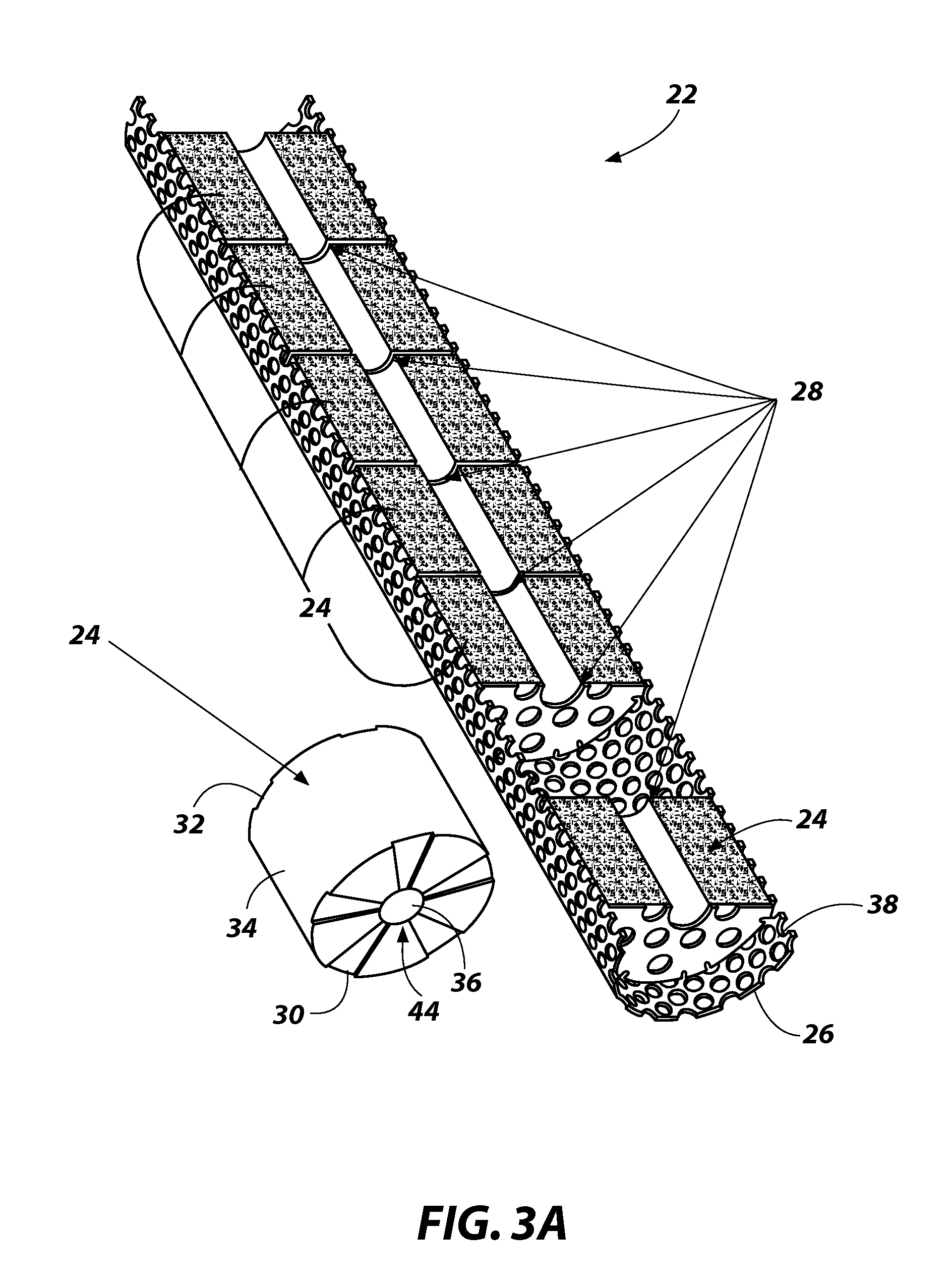
[0023]A gas-generating device 22 according to an embodiment of the present invention is shown in FIGS. 3A and 3B. The gas-generating device 22 may include a plurality of gas-generant grains 24, a frame, such as a sleeve 26, and at least one retention structure, such as a retention plate 28. The plurality of gas-generant grains 24 may be constrained to a longitudinally stacked configuration by the sleeve 26 and each retention plate 28 may be coupled to the sleeve 26 and positioned between adjacent gas-generant grains 24 of the plurality of gas-generant grains 24. The gas-generating device 22 may be located within a combustion chamber of a gas-generating assembly (not shown), which may include an igniter and may be coupled to an effluent train.

[0024]Each gas-generant grain 24 may be substantially cylindrical or annular in shape. Accordingly, each grain 24 may include a substantially planar first end surface 30, a substantially planar second end surface 32, a generally arcuate outer su...


PUM

PropertyMeasurementUnit
outer diameteraaaaaaaaaa
inner diameteraaaaaaaaaa
dimensionaaaaaaaaaa

Abstract

Gas-generating devices with grain-retention structures and related methods and systems are described. In particular, gas-generating devices having at least one retention structure fixed to a frame and positioned between adjacent gas-generant grains arranged in a longitudinal stack. Fire suppression systems comprising such gas-generating devices are also described. Additionally, methods of manufacturing gas-generating devices, as well as methods of generating a gas and methods of suppressing a fire utilizing such gas-generating devices are described.

Description

CROSS-REFERENCE TO RELATED APPLICATION[0001]The present application is related to U.S. patent application Ser. No. 11 / 409,257 entitled MAN-RATED FIRE SUPPRESSION SYSTEM, filed on Apr. 21, 2006, pending; U.S. patent application Ser. No. 10 / 727,088 entitled MAN-RATED FIRE SUPPRESSION SYSTEM, filed on Dec. 2, 2003, pending; U.S. patent application Ser. No. 10 / 727,093 entitled METHOD AND APPARATUS FOR SUPPRESSION OF FIRES, filed Dec. 2, 2003, now U.S. Pat. No. 7,337,856 issued Mar. 4, 2008; and U.S. patent application Ser. No. 12 / 042,200 entitled METHOD AND APPARATUS FOR SUPPRESSION OF FIRES, filed Mar. 4, 2008, pending, the disclosures of all of which are incorporated by reference herein in their entirety.TECHNICAL FIELD[0002]The invention relates to gas-generating devices with grain-retention structures and related methods and systems. In particular, the invention relates to gas-generating devices having at least one retention structure positioned between gas-generant grains. The inve...

Claims


Application Information

Patent Timeline
Patent Type & Authority Applications(United States)
IPC IPC(8): A62C2/00C06B45/00A62C35/00B23P17/00
CPCB60R2021/2648F42B3/04F42B5/16Y10T29/494
Inventor ROBBINS, STEVEN M.SAMPSON, WILLIAM P.
Owner NORTHROP GRUMMAN INNOVATION SYST INC
Learn More