

Clamping assembly for clamping strings of stringing machine for sport rackets
- Summary
- Abstract
- Description
- Claims
- Application Information
AI Technical Summary
Benefits of technology
Problems solved by technology
Method used
Image

Examples
Embodiment Construction
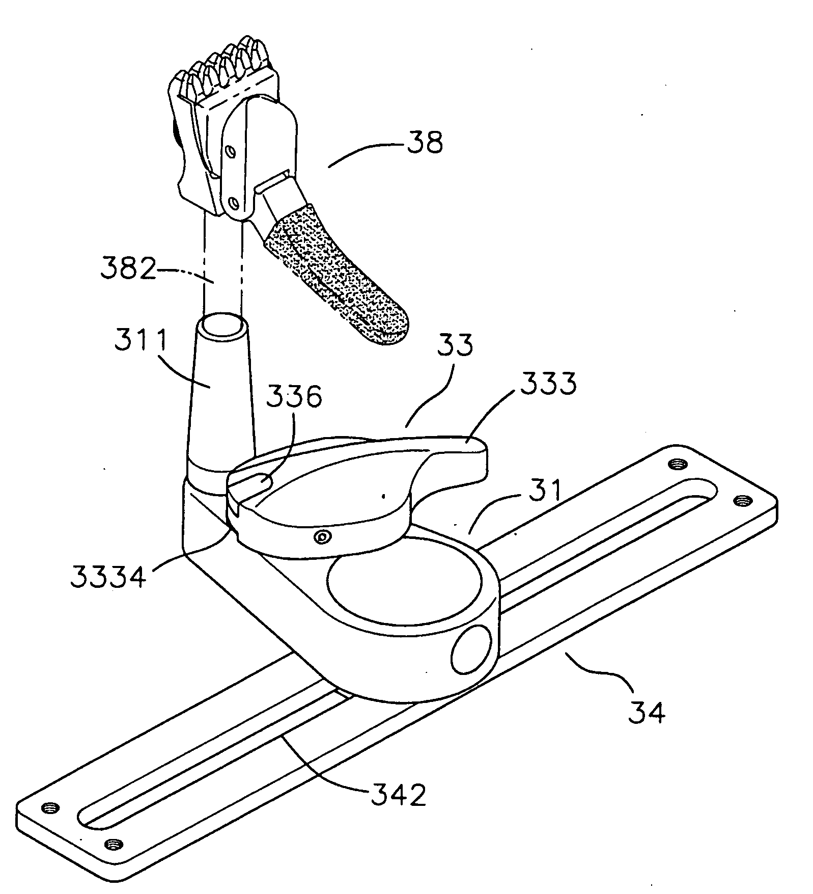
[0024]Referring to FIGS. 5 to 7, the clamping assembly of stringing machine of the present invention comprises a slide member 31, a positioning device 32, a control device 33 and a rail 34. The rail 34 is located at a top of the stringing machine and a slot 342 is defined in the rail 34. The positioning device 32 is located at an end of the slide member 31 and engaged with the slot 342. A tube 311 is located at the other end of the slide member 31. An extension 82 of a clamping device 38 is inserted into the tube 311. The control device 33 is located between the positioning device 32 and the tube 311.
[0025]The control device 33 includes a pin 331, a ring-shaped member 332 and a knob 333. The ring-shaped member 332 is engaged with the slide member 31 and the pin 331 is pivotably connected with the ring-shaped member 332. The pin 331 is pivotably connected with the knob 333. An annular space is defined in a top of the ring-shaped member 332 and a torsion spring 334 is received in the ...
PUM
 Abstract
Description
Claims
Application Information