Multiband antenna

a multi-band antenna and antenna technology, applied in the direction of resonant antennas, separate antenna unit combinations, radiating element structural forms, etc., can solve the problems of difficult miniaturization, complex structure of multi-band antennas, and difficulty in precise installation of multi-band antennas in portable electronic devices

Active Publication Date: 2010-12-09
CHI MEI COMM SYST INC
View PDF5 Cites 141 Cited by
  • Summary
  • Abstract
  • Description
  • Claims
  • Application Information

AI Technical Summary

Problems solved by technology

Generally, multiband antennas have complicated structures and are difficult to be miniaturized.
Furthermore once miniaturized, multiband antennas are difficult to be precisely installed in portable electronic devices.
Thus, communication quality of the portable electronic devices using the multiband antennas may be adversely affected.

Method used


Image

  • Multiband antenna
  • Multiband antenna
  • Multiband antenna

Examples


Embodiment Construction

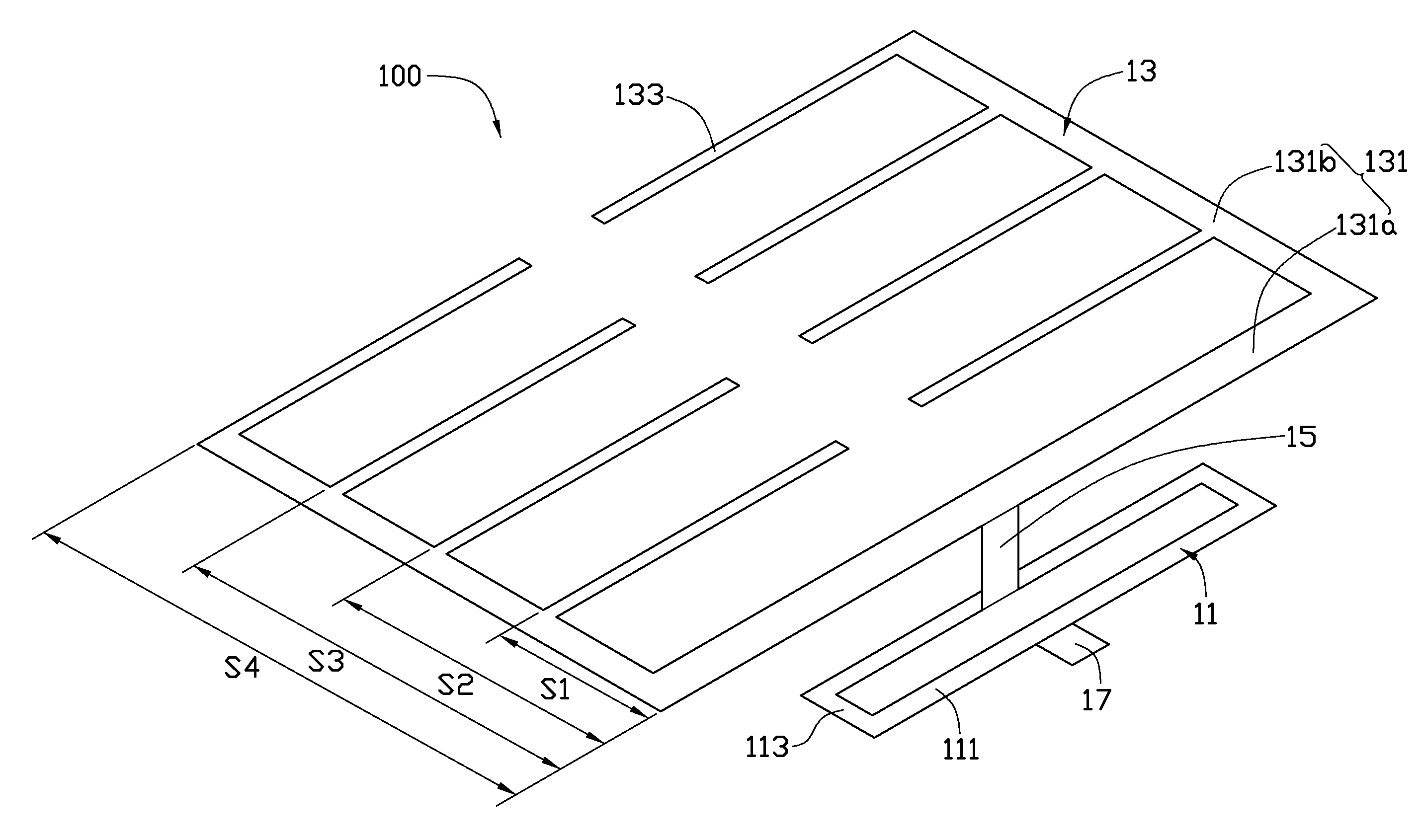
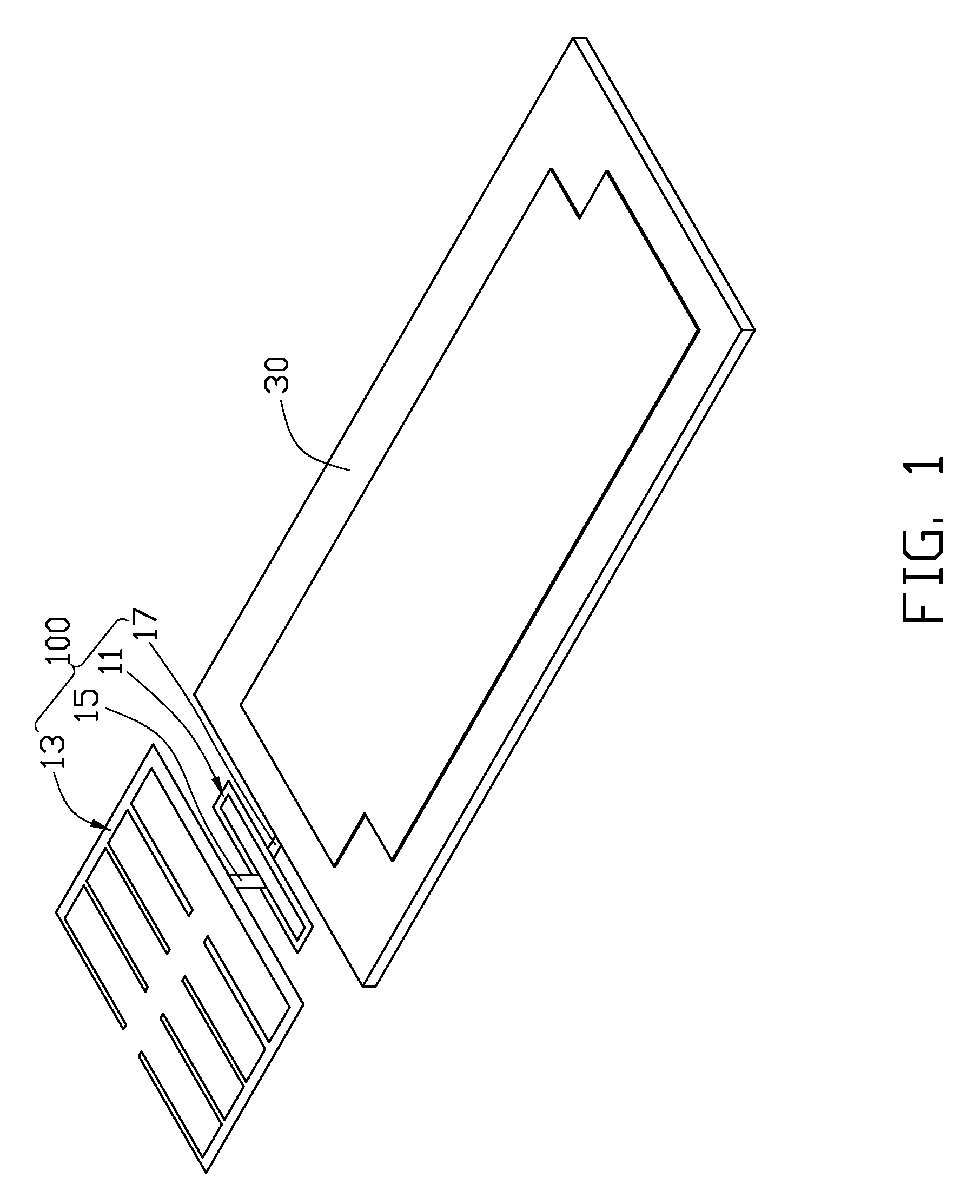
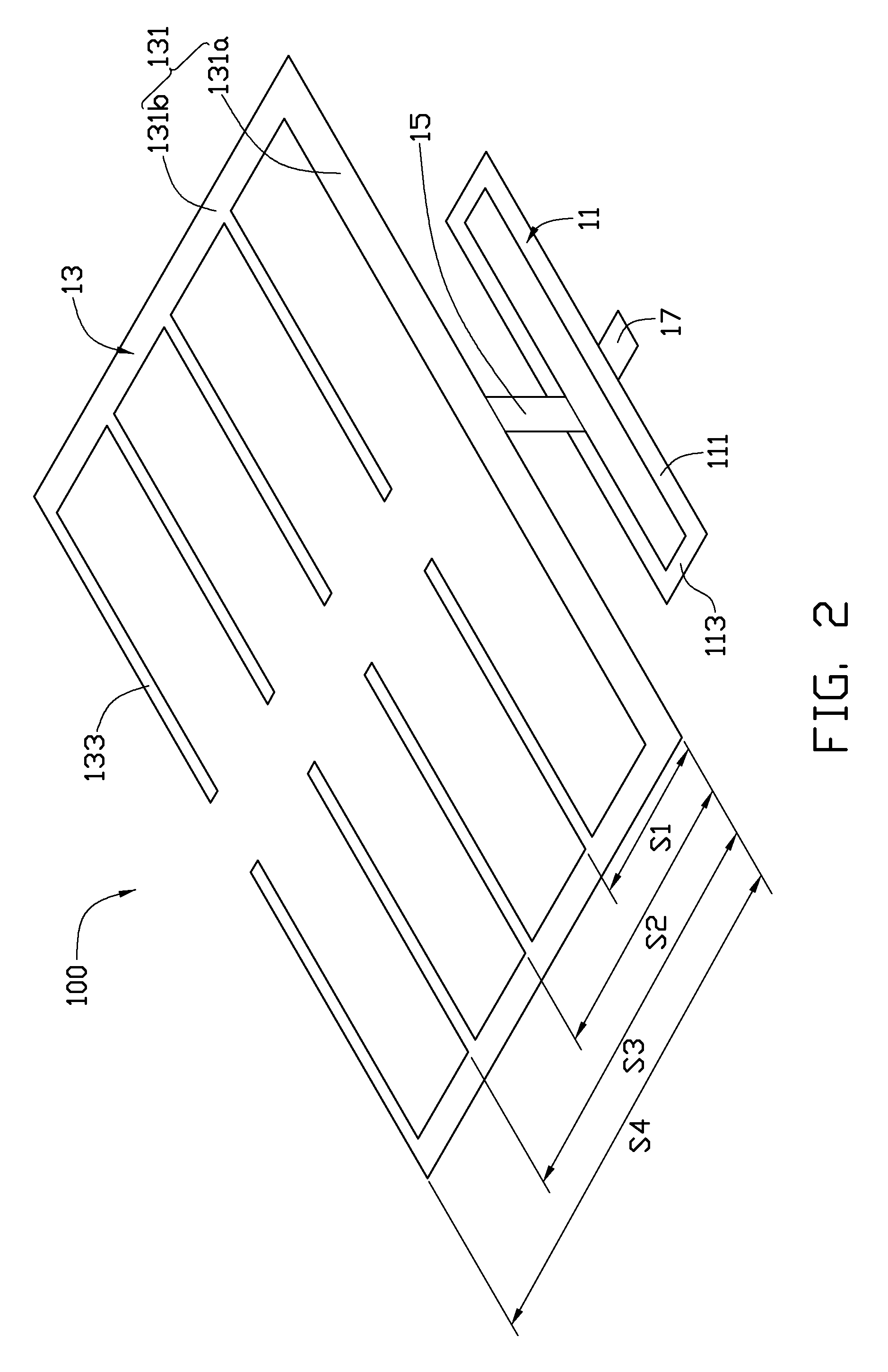
[0012]FIG. 1 and FIG. 2 schematically show a multiband antenna 100 according to an exemplary embodiment, for use in portable electronic devices. The multiband antenna 100 can be installed in a portable electronic device and connected to a conventional circuit board 30 of the portable electronic device to receive / send wireless signals when the portable electronic device is used.

[0013]The multiband antenna 100 includes a first radio unit 11, a second radio unit 13, a connecting unit 15, and a feed unit 17. The first radio unit 11 and the second radio unit 13 are both planar sheets made of conductive materials, and are parallel to each other. The first radio unit 11 can be a rectangular frame, i.e., a closed loop. The first radio unit 11 includes two relatively longer sides 111 parallel to each other, and two relatively shorter sides 113 parallel to each other and perpendicularly connected between the two relatively longer sides 111.

[0014]The second radio unit 13 includes an approximat...


PUM


Abstract

A multiband antenna includes a first radio unit closed loop and a second radio unit connected to the first radio unit and symmetrical structure. When the multiband antenna functions, the first radio unit functions as a balanced loop antenna, and the second radio unit functions as a dipole antenna.

Description

BACKGROUND[0001]1. Technical Field[0002]The present disclosure relates to multiband antennas, and particularly to multiband antennas used in portable electronic devices.[0003]2. Description of Related Art[0004]Nowadays, portable electronic devices, such as mobile phones, personal digital assistants (PDA) and laptop computers, are widely used. Most of these portable electronic devices have antennas mounted therein for receiving / sending wireless signals. Commonly, a portable electronic device may receive / send wireless signals of different frequencies, which requires its antenna be a multiband antenna.[0005]Generally, multiband antennas have complicated structures and are difficult to be miniaturized. Furthermore once miniaturized, multiband antennas are difficult to be precisely installed in portable electronic devices. Thus, communication quality of the portable electronic devices using the multiband antennas may be adversely affected.[0006]Therefore, there is room for improvement wi...

Claims


Application Information

Patent Timeline
Patent Type & Authority Applications(United States)
IPC IPC(8): H01Q21/30H01Q1/38H01Q5/10
CPCH01Q3/30H01Q3/26
Inventor TSOU, TUN-YUANLEE, YI-CHIEH
Owner CHI MEI COMM SYST INC
Why Eureka
Try Eureka