Methods and apparatus for a low reflectivity compensated antenna

Active Publication Date: 2010-12-09
SYMBOL TECH LLC
View PDF13 Cites 21 Cited by
  • Summary
  • Abstract
  • Description
  • Claims
  • Application Information

AI Technical Summary

Benefits of technology

[0008]An antenna in accordance with one embodiment of the present invention includes a dipole radiator region comprising a series resonant tank having a first quality factor value Q1, and a loop compensator/radiator region integral with the dipole region and comprising a

Problems solved by technology

An antenna system that meets such stringent performance guidelines represents a considerable deviation from conventional antenna requirements.
Very few antennas have ever been manufactured to the tighter specification for two reasons: There are very few designs that can maintain that performance over the required frequency range, and such an endeavor impacts the manufacturing yield

Method used


Image

  • Methods and apparatus for a low reflectivity compensated antenna
  • Methods and apparatus for a low reflectivity compensated antenna
  • Methods and apparatus for a low reflectivity compensated antenna

Examples


Embodiment Construction

[0020]The following discussion generally relates to improved methods and apparatus for antenna systems used in connection with mobile devices. In that regard, the following detailed description is merely illustrative in nature and is not intended to limit the invention or the application and uses of the invention. Furthermore, there is no intention to be bound by any expressed or implied theory presented in the preceding technical field, background, brief summary or the following detailed description. For the purposes of conciseness, conventional techniques and principles related to antennas, RF communication, and the like need not and will not be described herein.

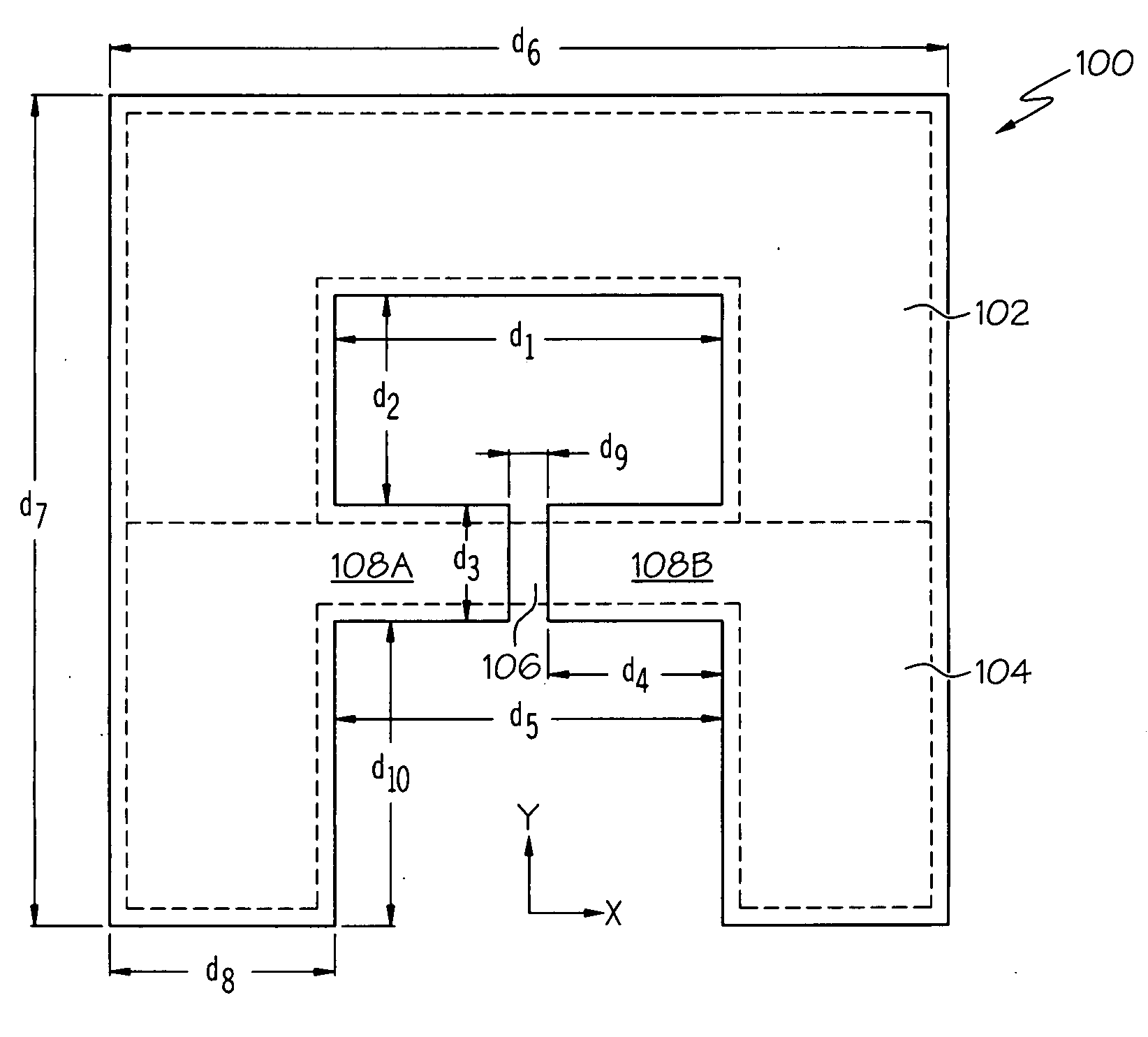
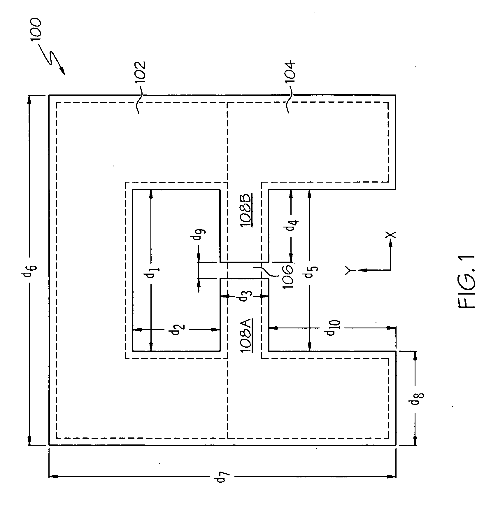
[0021]Referring now to FIG. 1, an antenna 100 (e.g., a conductive sheet antenna) in accordance with one embodiment of the present invention generally includes a dipole radiator region 104 (bounded by a set of dotted lines) and a loop compensator / radiator region 102 (also bounded by a set of dotted lines). The two regions 1...


PUM


Abstract

An antenna includes a dipole radiator region forming a series resonant tank having a first quality factor value Q1, and a loop compensator/radiator region integral with the dipole region and forming a parallel resonant tank having a second quality factor value Q2 that is substantially equal to Q2. The antenna may be a conductive sheet antenna (e.g., comprising copper tape) having a generally “A” shaped structure with a discontinuity in a middle segment.

Description

TECHNICAL FIELD[0001]The present invention generally relates to antenna technology, and more particularly relates to compensated antenna systems used in connection with mobile devices.BACKGROUND[0002]Mobile devices, such as hand-held computers, RFID readers, and the like, are used in a variety of contexts. Such devices typically include one or more antenna elements to facilitate RF communication.[0003]Modern, high performance radio systems are capable of providing an unusually high receiver dynamic range and high receiver-to-transmitter isolation performance only if they are connected to an antenna system that possesses an extremely small S11 voltage reflection coefficient (e.g., about −30 dB) across an operating band width of, for example, three percent. A UHF mono-static RFID Reader system (one that uses a single antenna for transmitting and receiving) is one example of such a system. A CW Radar system is another example.[0004]An antenna system that meets such stringent performanc...

Claims


Application Information

Patent Timeline
IPC IPC(8): H01Q1/00H01Q1/38
CPCH01Q1/2216H01Q21/29H01Q9/285H01Q7/00H01Q13/106H01Q19/30H01Q21/24H01Q21/30H01Q5/364
Inventor DURON, MARKKNADLE, RICHARD
Owner SYMBOL TECH LLC
Why Eureka
Try Eureka